The AAPG/Datapages Combined Publications Database
AAPG Bulletin
Figure
AAPG Bulletin; Year: 2015; Issue: June DOI: 10.1306/01191513190
Return to Full Text
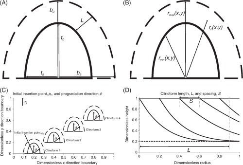
Figure 4
(A) A user specifies the length of the top (solid line) and base (dashed line) ellipses in depositional dip and strike directions ( ,
,  ,
,  ,
,  ; Table 1) relative to the clinoform origin. The surface representing the clinoform is created in the volume between the top and base ellipses. (B) At a point on the clinoform, the radius relative to the clinoform origin (black arrow,
  , the radius of the base ellipse (black arrow,
  and the radius of the top ellipse (black arrow,
  are calculated. (C) Plan view of four adjacent clinoforms. The user specifies the overall progradation direction of the clinoforms relative to north, as well as the coordinates of the initial insertion point
  . (D) Conceptual depositional-dip-oriented cross-section view of clinoforms. Clinoform spacing,
  , is defined as the distance between the top truncation points of two adjacent clinoforms. Clinoform length, L, is defined as the distance between the top and base truncations by the user-specified bounding surfaces along a single clinoform.
Figure 4
(A) A user specifies the length of the top (solid line) and base (dashed line) ellipses in depositional dip and strike directions (, , , ; Table 1) relative to the clinoform origin. The surface representing the clinoform is created in the volume between the top and base ellipses. (B) At a point on the clinoform, the radius relative to the clinoform origin (black arrow, , the radius of the base ellipse (black arrow, and the radius of the top ellipse (black arrow, are calculated. (C) Plan view of four adjacent clinoforms. The user specifies the overall progradation direction of the clinoforms relative to north, as well as the coordinates of the initial insertion point . (D) Conceptual depositional-dip-oriented cross-section view of clinoforms. Clinoform spacing, , is defined as the distance between the top truncation points of two adjacent clinoforms. Clinoform length, L, is defined as the distance between the top and base truncations by the user-specified bounding surfaces along a single clinoform.