The AAPG/Datapages Combined Publications Database
AAPG Bulletin
Figure
AAPG Bulletin; Year: 2016; Issue: May DOI: 10.1306/02011614118
Return to Full Text

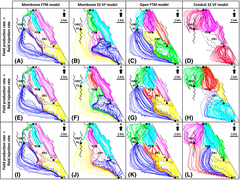
Figure 9. The streamlines in all simulated models for the three injection–production schemes. In each figure, different colors distinguish different streamlines of injector–producer pairs. FTM = fault transmissibility multiplier; I = water injector; OR = oil region; P = liquid producer; SZ = slip zone; VF = volumetric fault.

Figure 9. The streamlines in all simulated models for the three injection–production schemes. In each figure, different colors distinguish different streamlines of injector–producer pairs. FTM = fault transmissibility multiplier; I = water injector; OR = oil region; P = liquid producer; SZ = slip zone; VF = volumetric fault.