The AAPG/Datapages Combined Publications Database
Environmental Geosciences (DEG)
Full Text
![]() Click to view page images in PDF format.
Click to view page images in PDF format.
Environmental Geosciences, V.
DOI: 10.1306/eg.09261919016
Carbon dioxide storage resource assessment of Cretaceous- and Jurassic-age sandstones in the Atlantic offshore region of the northeastern United States
Isis Fukai,1 Laura Keister,2 Priya Ravi Ganesh,3 Lydia Cumming,4 Will Fortin,5 and Neeraj Gupta6
1Battelle Memorial Institute, Columbus, Ohio; present address: The Bredesen Center for Interdisciplinary Research and Graduate Education, University of Tennessee, Knoxville, Tennessee; [email protected]
2Battelle Memorial Institute, Columbus, Ohio; [email protected]
3Battelle Memorial Institute, Columbus, Ohio; [email protected]
4Formerly, Battelle Memorial Institute, Columbus, Ohio; [email protected]
5Lamont-Doherty Earth Observatory (LDEO), Columbia University, Palisades, New York; [email protected]
6Battelle Memorial Institute, Columbus, Ohio; [email protected]
ABSTRACT
Carbon capture and storage is a critical technology for ensuring a range of clean energy options are available to meet future energy demand in the United States and abroad. A total of 1079 industrial CO2 emission sources are located in the northeastern United States, where challenging surface and subsurface conditions limit onshore CO2 storage potential. A systematic resource assessment was conducted using industry-standard resource classification methods established by the Society of Petroleum Engineers’ Storage Resources Management System to characterize CO2 storage resources in the middle–northern Atlantic offshore region along the eastern United States. Storable CO2 quantities and storage efficiencies were estimated for Cretaceous- and Jurassic-age sandstone sequences. Regional data integration and analysis were conducted to estimate storable quantities and storage efficiencies using probabilistic methods with static volumetric calculations and dynamic simulations. Offshore storage efficiencies range from 1% to 13%, with regional-scale estimates of 37–403 billion t (Gt) of CO2 classified as prospective storage resources. Dynamic CO2 injection simulation in a middle Cretaceous sequence on the eastern flank of the Great Stone Dome suggests 30–51 million t of CO2 can be stored and contained within the time and pressure constraints assumed for a commercial storage project. The regional Cretaceous and Jurassic plays identified in the offshore study region have prospective storage resources sufficient for long-term storage of CO2 from nearby industrial sources onshore. Continued resource discovery efforts are recommended to assess the development and commerciality of the potential storage identified near the Great Stone Dome.
INTRODUCTION
Overview
Carbon capture and storage (CCS) is a critical technology for ensuring a range of clean energy options are available to meet current and future energy demand in the United States and abroad. This paper describes the methods and outcomes of a carbon storage resource assessment of deep saline geologic formations in the northern mid-Atlantic offshore region along the eastern United States. Storage resource assessment is an essential component of the site screening, selection, and characterization process necessary to successfully advance a CCS project through classification, development, and commercialization.
The northeastern and mid-Atlantic United States have 1079 industrial CO2 emission sources that emit over 25,000 million t (Mt) of CO2/yr (Environmental Protection Agency, 2018). This region has challenging surface and subsurface conditions that hinder large-scale implementation of onshore CO2 storage, such as high population density and the presence of basement and/or crystalline rocks at near-surface conditions along with the prevalence of faults and fractures and relatively low-porosity phanerozoic sedimentary rocks. These challenges currently restrict onshore carbon storage to small isolated areas in the northeast and mid-Atlantic United States, many of which also lack sufficient subsurface data to constrain storage resource estimates. This is supported by previous work that suggests limited onshore carbon storage potential may exist in localized areas of New Jersey, Delaware, and Maryland (Hovorka et al., 2013; Collins et al., 2017; Craddock et al., 2018). These difficult assessments encountered many challenges and restrictions imposed by the paucity of onshore deep-well data in northeastern states, especially in comparison to locations like Texas and Oklahoma that have abundant subsurface data from years of extensive characterization, exploration, development, and production activities associated with the oil and gas industry. The relatively minor role of the well industry (e.g., oil, gas, disposal) in northeastern and mid-Atlantic states suggests CCS projects could also potentially be impeded by public opposition and regulatory setbacks resulting from uncertainty and unfamiliarity with the well industry and subsurface development activities.
Perhaps one of the biggest challenges facing the northeastern United States is reducing greenhouse gas emissions from the numerous carbon-intensive industries in the region that produce CO2. The systematic approach and classification framework employed in this study are intended to establish a clear, common, and consistent communication standard to describe offshore storage resources with estimates of storable quantities provided in the context of uncertainty and commercialization potential defined by resource status. Use of the CO2 Storage Resources Management System (Society of Petroleum Engineers, 2017) guidelines to establish a common reference system and consistent nomenclature is key for improving communication and information sharing needed to advance CCS project development and support regulatory agencies, policy makers, stakeholders and investors, and industries in the northeastern United States. This approach can help to support a paradigm shift that’s emerging as part of a growing circular economy in the United States where CO2 may no longer be viewed as a burdensome waste stream in industry but rather a marketable byproduct of manufacturing and energy production. The CO2 Storage Resource Management System guidelines will also require an assessment of differences in CO2 sources, production methods, quantities, as well as qualities, with more CO2 viewed as a byproduct inherent to the manufacturing processes in the northeastern United States, rather than from fuel combustion alone (International Energy Agency, 2017). In the northeastern United States, carbon-intensive industries include those involved in the manufacturing and production of steel, iron, cement, carbon fibers, concretes, liquid fuels, chemicals refining, etc. The manufactured products and services provided by many of these industries are integral to the development and support of critical infrastructure systems in the United States. Currently, CCS is the only technology that can address CO2 emissions associated with these carbon-intensive industry operations (International Energy Agency, 2017).
If local onshore storage sites are not available or feasible for commercial storage in the northeastern United States, long-distance regional pipelines will be required to transport captured CO2 from these industries to the nearest onshore storage site(s) (e.g., in the Midwest). Otherwise, new manufacturing and production approaches may have to be adopted to reduce greenhouse gas emission in the northeastern United States. Carbon-intensive industries may apply production modifications to improve operational efficiency and decrease CO2 byproduct and/or implement plant conversions or customizations for lower-carbon source materials and products. These approaches may not be technically or economically feasible for all companies in the region, which may result in these companies resorting to downscaling and/or decreasing production to reduce greenhouse gas emissions or pivoting away from carbon-intensive markets.
Alternatively, it has been reported that the greatest potential for carbon storage in the northeastern United States lies in the offshore geologic formations comprising the continental shelf (Schrag, 2009). Offshore storage can be implemented close to large CO2 emission point sources from both carbon-intensive industries and the power generation sector, helping to avoid many of the logistical difficulties, storage limitations, and potential risks encountered when siting onshore projects in the northern East Coast of the United States.
Offshore carbon storage has been successfully implemented at Norway’s Sleipner storage site in the North Sea since 1996, and a second offshore storage site, Snøhvit, has been in operation since 2008 (Furre et al., 2017). In 2016, Norway initiated full-scale deployment through the Norwegian CCS demonstration project (Ringrose, 2018). The Sleipner site was initially motivated by Norway’s offshore carbon tax, but the development of offshore storage has also been influenced by the public perception of onshore storage and the favorable offshore subsurface conditions (Anthonsen et al., 2013; Monastersky, 2013). The United Kingdom, Poland, and South Korea are also taking steps toward developing offshore storage in the 2020s to reduce greenhouse gas emissions and use existing offshore infrastructure (Milligan, 2014; Kim et al., 2016).
Objectives
This study presents a comprehensive geologic carbon storage resource assessment for the mid-Atlantic offshore region extending along the eastern United States from Massachusetts in the north to Virginia in the south. Previous work has provided initial estimates of offshore CO2 storage via preliminary dynamic models and high-level volumetric estimates conducted in localized areas of the mid-Atlantic offshore region, mostly in the northern Baltimore Canyon Trough (e.g., Brown et al., 2011; Midwest Regional Carbon Sequestration Partnership, 2011). However, a systematic, regional-scale resource assessment using industry standards for quantifying, classifying, delineating, and down selecting CO2 storage resources has not yet been conducted for this region. To address this need, we employ a comprehensive, multiscale storage resource assessment that uses the classification framework set forth in the CO2 Storage Resources Management System (Society of Petroleum Engineers, 2017) along with recommended best practices for geologic storage site screening, selection, and characterization for CO2 storage resources established by the US Department of Energy’s Regional Carbon Sequestration Partnerships (US Department of Energy National Energy Technology Laboratory, 2017).
This study examines storage resources at the regional scale using static volumetric calculations with heterogeneous grid data and stochastic analysis. Regional results and subbasin observations are used to delineate a selected area for local-scale resource classification and refinement of estimated storable quantities. The systematic approach and classification framework employed in this study are intended to establish a clear, common, and consistent communication standard to describe offshore storage resources, with estimates of storable quantities provided in the context of uncertainty, and commercialization potential defined by resource status. Use of this common reference system and consistent nomenclature is key for improving communication and information sharing needed to advance CCS project development and support regulatory agencies, policy makers, stakeholders and investors, and industries in the northeastern United States (e.g., SPE Storage Resources Management System [SRMS]).
Study Area and Geologic Background
The offshore study area encompasses approximately 171,000 km2 (∼66,023 mi2) along the mid-Atlantic states of Virginia, Maryland, Delaware, New York, New Jersey, and Pennsylvania. The study area comprises three major subregions: Georges Bank Basin, Long Island platform, and Baltimore Canyon Trough (Figure 1). The study area extends from within 10 to 300 km (6–186 mi) offshore, encompassing the inner continental shelf to portions of the continental slope.
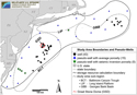 Figure 1. Map showing the locations of pseudowells used to constrain porosity map grids for storage resource calculations. CT = Connecticut; DE = Delaware; MA = Massachusetts; MD = Maryland; NJ = New Jersey; NY = New York; PA = Pennsylvania; RI = Rhode Island.
The mid-Atlantic United States passive continental margin contains thick (2–16 km [1–10 mi]) postrift Lower Jurassic and younger sediments in offshore basins and thinner (0–2.4 km [0–1.5 mi]) uppermost Jurassic–Holocene sediments on the onshore coastal plain (e.g., Grow and Sheridan, 1988). The offshore basins contain a thick succession of Jurassic–Paleogene sedimentary rocks above crystalline basement that lies at depths of 5–15 km (3–9 mi). Structural and stratigraphic traps have been identified in each offshore basin area via analysis of two-dimensional seismic lines and sequence stratigraphic relationships (e.g., Scholle, 1977; Schlee, 1980; Brown et al., 2011; Midwest Regional Carbon Sequestration Partnership, 2011). In the northern Baltimore Canyon Trough, structural closures form above an Early Cretaceous igneous intrusion called the Great Stone Dome and structural highs interpreted as broad grabens and/or deeply buried reef deposits atop carbonate platforms (e.g., Schlee et al., 1976; Poag, 1978; Jansa and Pe-Piper, 1988). In the northeastern Georges Bank Basin, the structure of Lower Cretaceous and Upper Jurassic strata is dominated by the Yarmouth Arch, with beds dipping away from the northwest-southeast–oriented axis of the arch (Smith et al., 1976; Savva et al., 2016).
The sedimentary rocks of interest as cap rocks and storage zones consist of Jurassic- and Cretaceous-age mudstone, shale, and sandstone sequences that generally dip to the east-southeast toward the continental slope (Libby-French, 1984). Previous studies have identified porous and permeable sandstone units in middle Cretaceous, Lower Cretaceous, and Upper Jurassic sequences at depths ranging from approximately 800 to 4000 m (∼2600–13,000 ft) (e.g., Scholle, 1977; Amato and Bebout, 1980; Slater et al., 2010; Midwest Regional Carbon Sequestration Partnership, 2011). This interval is overlain by Upper Cretaceous mudstone and shale that extends regionally across the study area and is considered to be a primary barrier (cap rock) to ensure CO2 storage confinement. High-level static storage resource estimates reported in previous work suggest storage potential exists in Cretaceous-age sandstones in the northern Baltimore Canyon Trough subbasin (Midwest Regional Carbon Sequestration Partnership, 2011; Cumming et al., 2017). Preliminary dynamic simulation studies in previous work led by Schlumberger in the northern Baltimore Canyon Trough reported total injection rates as high as 6 Mt CO2/yr achieved in Cretaceous sedimentary rocks via eight injection wells in areas near and around the Great Dome structure (Brown et al., 2011).
METHODS
Workflow
This study involves the compilation and integration of data from offshore stratigraphic test wells and petroleum exploration wells, analog data from onshore coastal plain studies, and publicly available seismic survey data. The storage resource assessment workflow was optimized to address or minimize data gaps and uncertainties associated with sparse data distribution over a large region. This involved extensive efforts in data compilation, preservation, digitization, and integration into map grids and models. The resulting database was used to define offshore-specific site selection criteria and calculate offshore-specific probability values for storage efficiency parameters that were used, respectively, to help identify regional storage resources and inform volumetric estimates of storable quantities for deep saline reservoirs of interest. Localized estimates of storable quantities derived from simplified dynamic models and site-specific storage efficiencies are reported for a selected area near the Great Stone Dome structure. The results of this work provide a foundation for future CCS development efforts in the mid-Atlantic offshore region when the market conditions are appropriate.
As part of this study, a systematic workflow has been employed to quantify and categorize CO2 storage resources for the mid-Atlantic United States offshore region extending from Maryland to Massachusetts. This involves (1) data integration and physical property mapping, (2) regional-scale storage resource calculations, and (3) local-scale storage resource calculation refinement. Results from each subregion were used to delineate selected areas to refine static prospective resource estimates and conduct dynamic simulations of CO2 injection and storage performance for zones of interest.
Risk factors identified as part of this project, such as basin age and maturity, sediment lithification, and hydrostatic pressures, were integrated with recommended best practices for onshore geologic CO2 storage (US Department of Energy National Energy Technology Laboratory, 2017) to develop the following screening criteria for offshore storage resource assessment.
• Formation depth must be adequate (∼1000 m [∼3000 ft]) to ensure the (1) temperature and pressure conditions are suitable to store CO2 in a supercritical phase and (2) sediment is sufficiently consolidated such that the risk of soft-sediment deformation is minimized (Battelle, 2018).
• A suitable seal or cap rock overlies the targeted storage zone to inhibit the vertical migration of CO2 to the surface.
• Hydrogeologic conditions such as structural, stratigraphic, and hydrodynamic traps are present to retain the injected CO2 within the targeted storage zone(s).
These screening criteria were used along with structural, stratigraphic, and petrophysical analysis to define storage resource calculation boundaries, estimate offshore-specific storage efficiencies, and calculate CO2 storage resources for three deep saline formations of interest. The general workflow used for storage resource calculations is shown in Figure 2. Well logs and geologic samples (whole core, sidewall core, and drill cuttings) from continental offshore stratigraphic test wells and petroleum exploration wells drilled in the Atlantic Outer Continental Shelf were compiled, inventoried, and assimilated along with publicly available seismic data and historical well records to support the storage resource assessment. With legacy seismic data and relatively sparse well data available over the 171,000 km2 (66,000 mi2) study area, challenges associated with subsurface data gaps and uncertainty were incorporated into the storage resource assessment workflow.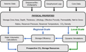 Figure 2. Schematic showing data input and workflow used for estimating offshore CO2 storage resources.
Geophysical logs from 44 existing offshore wells were scanned and digitized by project team members at the Pennsylvania Geological Survey to inform interpretations of storage zone sequence stratigraphy, lithofacies, and petrophysical properties. Seismic and well-log sequence stratigraphy was used to map and define the structural and stratigraphic framework of the cap rocks and storage zones. Biostratigraphic data provided age control to help align and correlate storage zone lithofacies with sequence boundaries. New laboratory analyses were conducted on 75 existing core samples (68 from the Baltimore Canyon Trough and 7 from the Georges Bank Basin) stored at the Delaware Geological Survey core repository to supplement and validate existing core data compiled from historical well records. Log data were integrated with new and existing laboratory-derived core analyses to better characterize effective reservoir lithology, porosity, and permeability. The newly reprocessed seismic data provided by this project were also used to derive estimates of porosity in areas without well data.
The integrated data set was used to develop regional depth, thickness, and porosity maps for each storage zone. Map grids served as input for regional-scale CO2 storage resource calculations using the static volumetric methodology and CO2 Storage Prospective Resource Estimation Excel Analysis (CO2-SCREEN) tool (version 1) (Sanguinito et al., 2016) developed by the US Department of Energy National Energy Technology Laboratory (DOE-NETL) (Goodman et al., 2011, 2016) for onshore deep saline formations. Offshore formation-specific storage efficiency values were determined using regional geospatial and statistical distributions of net-to-gross reservoir pore volume and permeability for the three storage zones of interest. Regional results were mapped, and locations exhibiting high CO2 storage resource (≥2.5 Mt CO2/km2 [≥6.5 Mt CO2/mi2]) constrained by data from three or more nearby wells were selected as potential injection sites for dynamic simulation.
Subsurface Data Integration and Analysis
Structural and Stratigraphic Framework
Regional interpretation and correlation of seismic data were used to define the structural and stratigraphic framework of offshore Cretaceous and Jurassic sequences, with three storage zones and two cap rocks identified in the Baltimore Canyon Trough (Figure 3) and three storage zones and three cap rocks identified in the Georges Bank Basin. Interpreted seismic horizons for each of the storage zones and cap rocks identified in this project were depth converted, tied to nearby wells, and integrated into a continuous, interpolated two-dimensional grid surface and three-dimensional geologic model to derive regional structure and thickness maps. A quality assurance and quality control procedure was performed to ensure seismic horizons, biostratigraphic markers, well-log sequence stratigraphic picks, and well-log lithostratigraphic picks were consistent to within ±100 m (±328 ft). Storage zone and caprock structure and depth were evaluated against screening criteria (Workflow subsection) to delineate storage resource calculation boundaries.
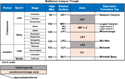 Figure 3. Correlation of chrono-, sequence, and seismic stratigraphy and formation tops used to define storage zone tops and bases for the Baltimore Canyon Trough. LK = Lower Cretaceous; MK = middle Cretaceous; UJ = Upper Jurassic; UK = Upper Cretaceous.
Petrophysical Analysis
Petrophysical analysis was conducted for quality assurance and quality control purposes and to integrate all available core and log data in the study region to generate effective porosity and permeability logs needed for calculation of offshore-specific storage efficiencies and storage resource estimates. The workflow for core and log data integration and development of the effective porosity and permeability curves is shown in Figure 4. All petrophysical calculations were conducted in Petra® for the three deep saline storage zones of interest. Aside from the structural and stratigraphic analysis described above, additional analyses of caprock properties, such as mineralogy and geomechanics, were not incorporated into the scope this assessment.
 Figure 4. Workflow used to integrate core and log data and generate effective porosity and permeability logs.
Log Data
A maximum gamma-ray cutoff of 75 API gamma-ray units (gAPI) is an industry standard for distinguishing between clean sandstone and carbonate reservoirs with low amounts of radioactive components (gamma ray <75 gAPI) and nonreservoir shale and clay-bearing rocks with higher proportions of radioactive constituents (e.g., Slatt, 2006). Gamma-ray logs were normalized by zone as part of a quality control procedure to eliminate varying signal intensities and establish consistent readings for sandstone, carbonate, and shale lithologies. Normalization was based on caprock and storage zone statistics from six type wells selected in the study area with gamma-ray data that generally fall within the normal ranges observed in shale and reservoir sandstones (Smith et al., 1976; Amato and Bebout, 1980). This normalization procedure ensured mineralogically homogenous (i.e., clean) sandstones and carbonates had gamma-ray values less than 75 gAPI and shale- and clay-rich intervals had values above 75 gAPI. Values of 75 gAPI and above were assumed to represent a spectrum of clay-bearing, nonreservoir lithologies ranging from muddy sandstone and carbonate to impermeable shale. Other logs used for characterization of reservoir lithology and petrophysical properties include bulk density, sonic, photoelectric, neutron porosity, density porosity, and sonic porosity logs.
Shale, Sandstone, and Carbonate Fractions
Effective porosity and reservoir facies were evaluated by assuming clean carbonate and sandstone represent potential storage reservoirs. Lithologic logs representing fractions of shale and reservoir components were initially generated from gamma-ray log data. Mineral and elemental concentrations from core data were then used to better constrain lithology and calibrate and supplement the lithofacies log data. Petrographic analysis, x-ray diffraction, and x-ray fluorescence were used to derive semiquantitative estimates of bulk-rock mineralogy and geochemistry. The x-ray diffraction was conducted on 75 whole core and sidewall core samples using a Panalytical Empyrean x-ray diffractometer and HighScore Plus software with the International Centre for Diffraction Data PDF-4 database (Degen et al., 2014; International Centre for Diffraction Data, 2018). Replicate analyses of nine samples were run as a test of precision, and semiquantitative results were interpreted using the Rietveld method (Rietveld 1967, 1969). Measurements of bulk-rock geochemistry via x-ray fluorescence were conducted on 76 whole core and sidewall core samples using a portable Thermo Scientific Niton™ XL3t GOLDD+ handheld analyzer and a built-in TestAllGeo calibration. Both sandstone and carbonate percentages were included in the estimated reservoir fraction.
Porosity
Lithofacies logs were used to calculate effective porosity curves by calculating the porosity associated with the reservoir fraction. The effective porosity log was normalized and spliced with core data to ensure the statistical distributions of log porosities were the same as that observed for the core data to be used in porosity–permeability transforms. The resulting final log was used to generate porosity map grids for storage resource calculations and derive permeability curves from porosity–permeability transform equations.
Pseudowells and Seismic Inversion Porosity
A total of 20 pseudowells were created to better constrain porosity map grids in areas with well data gaps (Figure 1). Zone top and base depths were assigned to pseudowells by sampling the depth grids derived from seismic surfaces to each pseudowell. The seismic inversion process used prestack waveform inversion to recover detailed information about the subsurface from the entire record of seismic amplitudes and phase spectra. The inversion methodology employs a genetic algorithm using the principles of natural evolution to converge on a globally optimum result (Mallick, 1995). The algorithm yielded a close correlation (∼85%) between real and modeled data. Using the inverted seismic velocities, a porosity model was derived from the empirical relationship with the primary wave velocity based on the empirical global relationship from Erickson and Jarrard (1998) that is fitted to sediments with normal consolidation histories.
Average effective porosities from the 3 nearest wells were assigned to storage zones in 15 pseudowells. Porosities derived from seismic inversion methods were used to characterize storage zone porosity in five pseudowells. The porosity values derived from seismic inversion exhibit mean values similar to that of the well data for each storage zone of interest, although with a smaller overall range and less variability because of the limited vertical resolution of the seismic wavelet (Figure 5).
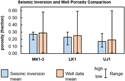 Figure 5. Comparison of porosity means and ranges from seismic inversion and effective porosity log data from wells for the three storage zones of interest. LK1 = Lower Cretaceous 1; MK1-3 = middle Cretaceous 1–3; UJ1 = Upper Jurassic 1.
Permeability Transforms
Porosity and permeability core data compiled from historical well records and new laboratory measurements acquired for this project were used to derive porosity–permeability transforms and generate permeability logs for each storage zone of interest. There were 914 unique porosity and permeability core data points in the combined data set for the three storage zones. Figure 6 shows the resulting plots of permeability and porosity with the calculated transform relationship used to derive permeability log curves for each zone. Relative to the transforms for the Lower Cretaceous 1 and Upper Jurassic 1, the particularly low correlation coefficient value observed in the regression for the middle Cretaceous 1–3 represents a source of inaccuracy and uncertainty in the permeability curve derived for this zone. The transform equation for each storage zone was applied to the effective porosity log in all wells to generate an estimated permeability curve. All core permeability data available for an individual well were then spliced directly into the permeability log.
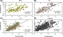 Figure 6. Porosity–permeability transforms derived from core data for the (A) middle Cretaceous 1–3 (MK1-3), (B) Lower Cretaceous 1 (LK1), (C) Upper Jurassic 1 (UJ1), and (D) all three storage zones combined. R2 = correlation coefficient.
Reservoir Pore Volume Grids
Total and net reservoir intervals were quantified and mapped using lithofacies logs to delineate clean sandstone reservoir intervals and using permeability as a proxy for connected pore volumes. Using a permeability cutoff of 10 md or greater and a lithologic cutoff for clean sandstone, petrophysical properties were calculated and mapped to generate regional two-dimensional grids representing the total reservoir pore volume in each storage zone.
Regional Storage Resource and Storage Efficiency Estimation
Static CO2 storage calculations employ estimates of subsurface pore volumes and in situ fluid quantities to derive an equivalent volume of CO2 that could occupy the pore space in a given storage reservoir. Several organizations and authors have developed static- and volumetric-based methodologies to estimate static CO2 storage potential in deep saline formations, including the Carbon Sequestration Leadership Forum (Bachu et al., 2007; J. Bradshaw et al., 2007; Carbon Sequestration Leadership Forum, 2007, 2008; US Department of Energy National Energy Technology Laboratory, 2008, 2010, 2012; B. E. Bradshaw et al., 2011; Goodman et al., 2011), the US Geological Survey (Zhou et al., 2008; Brennan et al., 2010; Szulczewski et al., 2012; Blondes et al., 2013), and international organizations such as CO2 GeoCapacity (Vangkilde-Pedersen et al., 2009). The static methodology developed by DOE-NETL was used to quantify and map the prospective CO2 storage resource of the offshore deep saline formations of interest (e.g., US Department of Energy National Energy Technology Laboratory, 2010; Goodman et al., 2011, 2016). This methodology is represented by equation 1:
The equation used to estimate offshore resources includes the total area (A), the net thickness (h), and the average effective porosity (ϕ) of the reservoir with gamma ray <75 gAPI and permeability (k) ≥ 10 md to represent the total pore volume. This total pore volume is then reduced via the storage efficiency factor (Esaline) to represent the fraction of the pore volume that will be occupied by CO2 (Goodman et al., 2011, 2016). The density of CO2 at reservoir conditions (ρCO2res) is used to equate the CO2-occupied pore volume to a mass of stored CO2 (GCO2). The Esaline parameter as defined by DOE-NETL is the product of five individual efficiency factors (US Department of Energy National Energy Technology Laboratory, 2008, 2010, 2012; Goodman et al., 2011). These individual efficiency parameters are shown in equation 2:
The net-to-total area (EAn), net-to-gross thickness (Ehn), and effective-to-total porosity (Eϕe) parameters are geologic terms that represent the net effective pore volume. The net effective pore volume is calculated as the ratio of the net pore volume with a permeability greater than or equal to 10 md relative to the net reservoir pore volume with a permeability of greater than or equal to 100 md. The two remaining efficiency factors are fluid displacement terms: volumetric displacement efficiency (EV), which represents the volume of rock surrounding an injection well that can be contacted by CO2 because of fluid conditions and mobility near the wellbore (sweep efficiency), and microscopic displacement efficiency (Ed) to account for irreducible water saturation.
Storage calculations were conducted using the CO2-SCREEN tool developed by DOE-NETL (Sanguinito et al., 2016). The tool employs equations 1 and 2 to stochastically estimate the storage resource of open-system saline formations. Its GoldSim Player module uses Monte Carlo sampling techniques and 10,000 realizations to achieve reasonable convergence for probabilistic resource estimates (Goodman et al., 2016; Sanguinito et al., 2016). Grid data generated from the depth, net thickness, and effective porosity maps were used as input for each storage zone. Reservoir pressure and temperature were based on regional pressure and temperature gradients (Battelle, 2018). The CO2 solubility model developed by Duan and Sun (2003) was used for CO2 density calculations.
Storage efficiency was evaluated in terms of geologic and displacement efficiency using statistical distributions from regional net-to-total pore volume grid data and outcome injection simulations. A second permeability cutoff of greater than or equal to 100 md was applied to the greater than or equal to 10-md reservoir interval to account for uncertainty in the estimated net pore volume available for CO2 storage. It represents an order of magnitude of potential error in the permeability curves calculated from porosity–permeability transforms.
To better facilitate the use of available data to define storage efficiency inputs, the three geologic efficiency terms, EAn, Ehn, and Eϕe, were combined into one parameter to represent the net-to-total reservoir pore volume efficiency such that
and equation 2 can be rewritten as
where the s superscript is added to the EPVn parameter to denote it as a stochastic calculation parameter defined by formation-specific data (Goodman et al., 2016). Probability (p) values of for the 10th percentile (P10) and 90th percentile (P90) of values were assigned to the geologic efficiency term based on statistical distributions of the pore volume ratios calculated from the grid cells in each storage zone.
Because of the site-specific nature of the displacement efficiency factors (Goodman et al., 2016; Sanguinito et al., 2016), volumetric displacement efficiency (EV) and microscopic displacement efficiency (Ed) were determined numerically (e.g., Frailey, 2013, 2014) using simple equivalent homogeneous models based on regional distributions of reservoir properties supported by well data in the middle Cretaceous 1–3 zone. High and low p values were derived from results of 90 injection simulations for the middle Cretaceous 1–3 zone. Key output performance metrics, such as CO2 saturation plume extent and amount of CO2 injected, were extracted from the model at the end of injection to calculate the displacement storage efficiency (Ev, Ed) factors (Frailey, 2013, 2014). The final storage efficiency (Esaline) value was calculated stochastically in CO2-SCREEN to derive GCO2 estimates at the P10, 50th percentile (P50), and P90 probability ranges.
Local-Scale Injection Simulation
Simplified dynamic simulations with Computer Modelling Group’s Generalized Equation-of-State Model were used in this study for two purposes: to (1) derive offshore-specific P10 and P90 values for the EV and Ed displacement efficiency parameters (equations 2 and 4) and (2) investigate the effects of pressure and operational conditions on CO2 injection and estimated CO2 storage resources for a selected area in the offshore study region. The area near the Great Stone Dome in the northern Baltimore Canyon Trough was selected based on results from regional static storage resource maps along with availability of well data. An interval at the top of the middle Cretaceous 3 zone having an average net thickness of 51 m (167 ft) was selected as the model injection zone.
A three-dimensional site model was then used to predict pressure response, CO2 injection and storage quantities, and CO2 plume saturation front for a simulated injection operation in the center of the middle Cretaceous 3 injection interval. Two primary injection scenarios were evaluated for the 30-yr simulation time frame, one using an injection rate of 1.5 Mt CO2/yr (reference injection scenario) and the second using a rate of 1.0 Mt CO2/yr (variant injection scenario). A maximum CO2 injection scenario was also examined, in which CO2 injection rates were adjusted to maintain the maximum allowable injection pressure measured at bottomhole conditions. The cumulative quantity of CO2 stored at the end of 30 yr was also calculated for a maximum CO2 injection scenario with injection rates defined by the maximum allowable injection pressure.
An X and Y grid increment of 50 m (164 ft) was defined around the injection well to cover the extent of the final CO2 plume, and an X and Y grid increment of 300 m (960 ft) was used toward the flanks of the model. Effective porosity and permeability logs from existing wells located within the model domain were rescaled to 1.5 m (5 ft) sample increments to divide the injection zone into vertical layers with unique porosity and permeability values for the dynamic simulation. All model boundaries were assumed to be closed to be consistent with structural trapping mechanisms identified in the selected area.
For the fluid model specification, the Peng-Robinson equation of state was used for the fluid model specification. The salinity of the formation brine was assumed to be 50,000 ppm, and Henry’s law was used to model CO2 solubility into the aqueous phase. The injection interval was assumed to be initially fully saturated with brine. The brine-saturated model was initialized at hydrostatic equilibrium. The fracture pressure constraint (translated to a maximum bottomhole pressure constraint) was honored and then shut in at the end of the simulation period. The injection well was perforated through the entire storage zone. A conservative maximum fracture pressure gradient of 14,703 Pa/m (0.65 psi/ft) was assumed for local-scale dynamic storage resource calculations (Brown et al., 2011).
RESULTS
Reservoir Petrophysical Properties
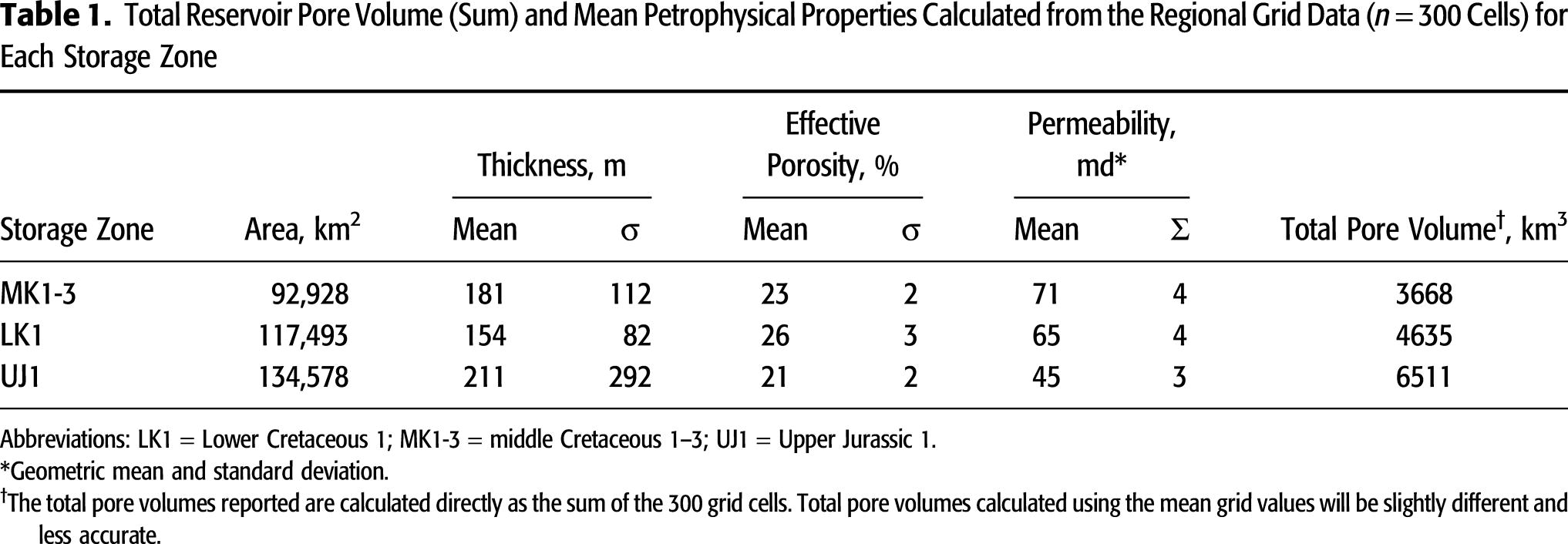
The petrophysical properties from the 300-grid-cell map data are summarized in Table 1 for reservoir intervals with permeability greater than or equal to 10 md in each storage zone of interest. The middle Cretaceous 1–3 exhibits an average thickness of 181 m (594 ft) and an average effective porosity of 23%, with map grid data for resource calculations covering an area of 92,928 km2 (35,880 mi2). The resulting total pore volume of the 300 grid cells representing the middle Cretaceous 1–3 reservoir interval with greater than or equal to 10-md permeability is 3668 km3 (880 mi3). The total area of volumetric grid data used in storage resource calculations for the Lower Cretaceous 1 zone is 117,493 km2 (45,364 mi2). The greater than or equal to 10-md reservoir interval in Lower Cretaceous 1 exhibits an average thickness of 154 m (505 ft) and an average effective porosity of 26%, for a total pore volume of 4635 km3 (1112 mi3). In the Upper Jurassic 1 zone, the greater than or equal to 10-md reservoir interval has an average thickness of 211 m (692 ft) and an average effective porosity of 21%. The resulting total pore volume calculated for the reservoir interval with greater than or equal to 10 md permeability in the Upper Jurassic 1 is 6511 km3 (1562 mi3). Thickness data from the Upper Jurassic 1 grid exhibit the highest standard deviation (292 m [958 ft]) of the three storage zones, followed by the middle Cretaceous 1–3 (112 m [367 ft]) and Lower Cretaceous 1 (82 m [269 ft]). Mean permeabilities of the greater than or equal to 10-md reservoir intervals range from 45 md in the Upper Jurassic 1 to 71 md in the middle Cretaceous 1–3 zone.
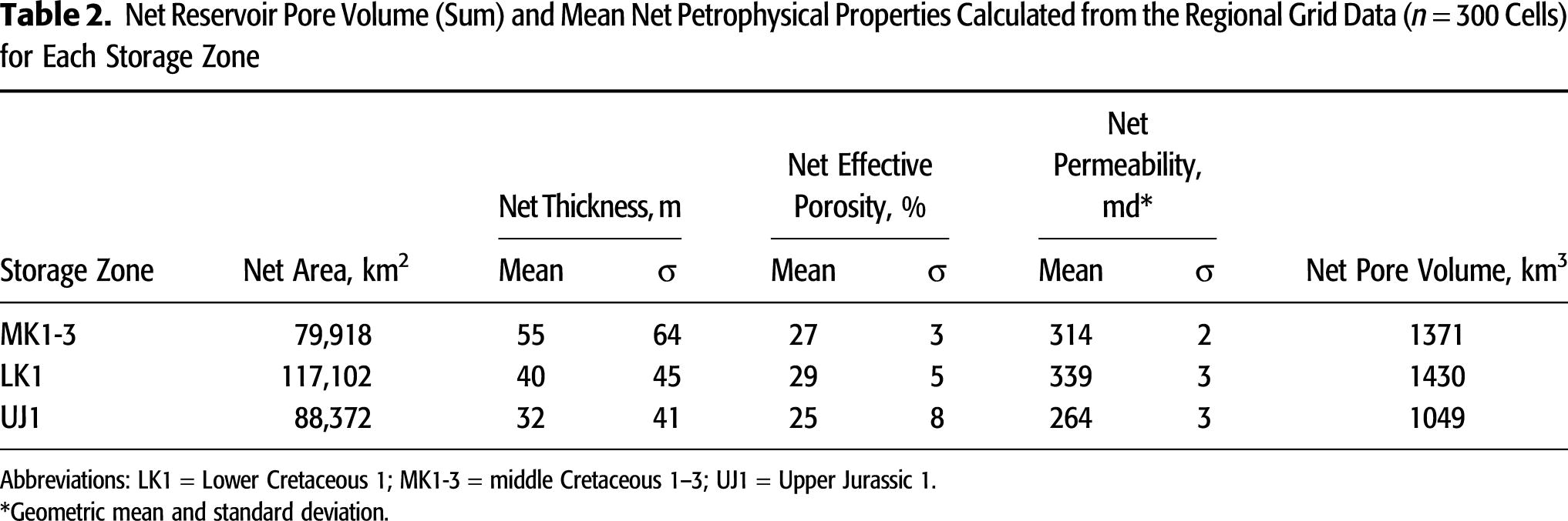
The petrophysical properties of the net reservoir interval with permeability greater than or equal to 100 md are summarized for each storage zone in Table 2. Relative to the Lower Cretaceous 1 and Upper Jurassic 1 storage zones, the net reservoir interval in the middle Cretaceous 1–3 zone exhibits the highest average net thickness of 55 m (180 ft) and the smallest net area of 79,918 km2 (30,857 mi2) with an average net effective porosity of 27% and a net reservoir pore volume of 1371 km3 (329 mi3). The Lower Cretaceous 1 exhibits the largest net area (117,102 km2 [45,213 mi2]), highest average net effective porosity (29%), and largest net reservoir pore volume (1430 km3 [343 mi3]) of the three storage zones evaluated. In contrast to the greater than or equal to 10-md cutoff used for total pore volume calculations, the greater than or equal to 100-md cutoff in the Upper Jurassic 1 zone results in the lowest net thickness (32 m [105 ft]) and smallest net reservoir pore volume (1049 km3 [252 mi3]) of the three storage zones. Mean permeabilities of 264, 314, and 339 md are estimated for the net reservoir intervals in the Upper Jurassic 1, middle Cretaceous 1–3, and Lower Cretaceous 1, respectively.
Offshore-Specific Storage Efficiency
The low (P10), median (P50), and high (P90) probability values derived for geologic and displacement efficiency components are shown in Table 3. The geologic efficiency values from the combined net-to-total pore volume data set from the three storage zones range from 0.10 (P10) to 0.58 (P90), with a median value of 0.31. The geologic efficiencies for the middle Cretaceous 1–3 zone exhibit the largest probability range. A median value of 0.36 is observed in both the middle Cretaceous 1–3 and Lower Cretaceous 1 zones. Upper Jurassic 1 exhibits the smallest geologic efficiency values and probability ranges of the three storage zones.
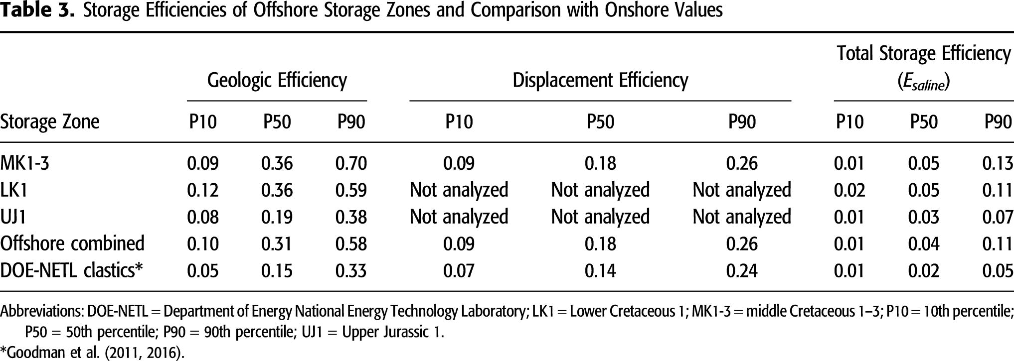
Offshore-specific displacement efficiencies range from 0.09 to 0.26, with a median (P50) value of 0.18. The displacement efficiency factors obtained in this study fall within the published range for onshore saline formations, with values between 0.07 to 0.24 reported over the P10 and P90 range for clastics by Goodman et al. (2011).
Using the combined data set of geologic and displacement efficiency values from the three storage zones, the resulting total storage efficiency estimates exhibit a range of 0.01–0.11 and a P50 of 0.04 (Table 3). Storage efficiency results are similar for middle Cretaceous 1–3 and Lower Cretaceous 1, with P50 values of 0.05 in both zones. The P90 value of 0.13 for the middle Cretaceous 1–3 storage efficiency distribution is slightly higher than the P90 value of 0.11 for the Lower Cretaceous 1 zone. The distribution of storage efficiency results for Upper Jurassic 1 has a P10 of 0.01, a P50 of 0.03, and a P90 of 0.07.
Regional Storage Resources and Storage Efficiency Estimates
Regional grid data representing total reservoir pore volumes were used as input along with the formation-specific storage efficiency p values to estimate and map the CO2 storage resources of each offshore storage zone. Storage resource estimates for the Lower Cretaceous 1 zone (Figure 7B) exhibit the highest P10 (59 billion t [Gt]) and P50 values (178 Gt) out of the three storage zones of interest, followed by the Upper Jurassic 1 (Figure 7C) and the middle Cretaceous 1–3 (Figure 7A). The regional-scale storage resources estimated for middle Cretaceous 1–3 range from 37 Gt (P10) to 378 Gt (P90), with a median P50 value of 148 Gt. The Upper Jurassic 1 storage resource estimates range from 54 Gt (P10) to 355 Gt (P90). The estimated storage resources for Lower Cretaceous 1 have the highest P90 value (403 Gt) of the three storage zones, followed by the middle Cretaceous 1–3 (378 Gt) and the Upper Jurassic 1 (355 Gt). The P10 and P90 values for the Upper Jurassic 1 exhibit the smallest range of the storage resource distributions calculated for the three offshore storage zones.
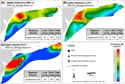 Figure 7. The regional 50th percentile (P50) static storage resource maps for the (A) middle Cretaceous 1–3 zone, (B) Lower Cretaceous 1 zone, and (C) Upper Jurassic 1 zone. The total calculated 10th percentile (P10), P50, and 90th percentile (P90) estimates are also shown for each storage zone. DE = Delaware; GRS = geodetic reference system; MD = Maryland; NAD83/UTM zone 19N = North American Datum 1983 Universal Transverse Mercator, zone 19 (northern hemisphere); NJ = New Jersey; PA = Pennsylvania; w/ = with.
The average storage resource per unit area for the middle Cretaceous 1–3 zone is approximately 1.60 Mt CO2/km2 (∼4.1 Mt CO2/mi2 [P50]). The highest storage resource values (>2.4 Mt CO2/km2 [>6.2 Mt CO2/mi2]) occur in the northern Baltimore Canyon Trough near the Great Stone Dome (Figure 7). Occurring along the southeastern extent of the middle Cretaceous 1–3 map boundary are P50 values less than or equal to 0.2 Mt CO2/km2 (≤0.5 Mt CO2/mi2). The average storage resource per unit area for the Lower Cretaceous 1 zone is approximately 1.52 Mt CO2/km2 (∼3.9 Mt CO2/mi2 [P50]). Lower Cretaceous 1 storage resource values greater than 2.4 Mt CO2/km2 (>6.2 Mt CO2/mi2 [P50]) are also observed in the northern Baltimore Canyon Trough near the Great Stone Dome. The P50 storage resource estimates for the Lower Cretaceous 1 in the eastern Georges Bank Basin range from approximately 0.8 Mt CO2/km2 (∼2 Mt CO2/mi2) in the southeast to 1.6 Mt CO2/km2 (4.1 Mt CO2/mi2) in the northwest. The P50 storage resource map for the Upper Jurassic 1 zone exhibits an average of 1.13 Mt CO2/km2 (2.9 Mt CO2/mi2). Estimates of 3.2 Mt CO2/km2 (8.3 Mt CO2/mi2) and higher are observed in the northern Baltimore Canyon Trough. Upper Jurassic 1 estimates range from approximately 0.4 to 3.4 Mt CO2/km2 (∼1–8.8 Mt CO2/mi2) in the eastern Georges Bank Basin, with values increasing to the northeast. Storage resource decreases to 0.2 Mt CO2/km2 (0.5 Mt CO2/mi2) along the southeastern margin of the Upper Jurassic 1 map boundary.
Local-Scale Injection and Storage Performance
The area near the Great Stone Dome in the northern Baltimore Canyon Trough was selected to simulate CO2 injection and storage performance under specific pressure, time, and operational constraints via simplified dynamic modeling. The three-dimensional site model covering an area of 596 km2 (230 mi2) was delineated by net thicknesses greater than or equal to 100 m (≥328 ft) and effective porosities greater than or equal to 20% for the Cretaceous–Jurassic interval extending from the middle Cretaceous 1–3 to the base of the Upper Jurassic 1 (Figure 8). The model injection well was positioned in the area with the highest net thickness, between three existing wells on the eastern margin of the Great Stone Dome. An interval at the top of the middle Cretaceous 3 zone, having an average net thickness of 51 m (167 ft), was identified as the most vertically and laterally continuous net pay interval (gamma ray <75 gAPI, permeability ≥100 md, and continuous pay thickness ≥6.1 m [≥20 ft]) within the Cretaceous–Jurassic section of interest and was selected as the model injection zone (Figure 9).
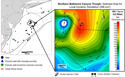 Figure 8. Local area in the northern Baltimore Canyon Trough (BCT) selected for dynamic CO2 injection simulation. DE = Delaware; LIP = Long Island platform; MD = Maryland; MK1 = middle Cretaceous 1; NJ = New Jersey; NY = New York; PA = Pennsylvania; UJ1 = Upper Jurassic 1; w/ = with.
 Figure 9. Structural cross section (see Figure 8 for areal transect) across the Great Stone Dome showing net pay flags calculated over the three storage zones and the selected injection zone for the dynamic reservoir simulation at the top of the middle Cretaceous. COST B-2 = Continental Offshore Stratigraphic Text well B-2; gAPI = API gamma-ray units; GR = gamma ray; k = permeability; LK1 = Lower Cretaceous 1; LK2 = Lower Cretaceous 2; MK1 = middle Cretaceous 1; MK2 = middle Cretaceous 2; MK3 = middle Cretaceous 3; PHIe = effective porosity; res = resistivity; UJ1 = Upper Jurassic 1; UK1 = Upper Cretaceous 1.
Three scenarios were evaluated for the 30-yr simulation time frame: a (1) maximum injection scenario in which injection rates are varied to maintain maximum injection pressures based on an assumed fracture pressure gradient of 14.7 kPa/m (0.65 psi/ft), (2) reference case using an injection rate of 1.5 Mt CO2/yr, and (3) variant case using a rate of 1.0 Mt CO2/yr.
The maximum amount of CO2 that could be injected over a 30-yr period was found to be 51 Mt for injection rates corresponding to the maximum allowable injection pressure of 31,000 kPa (4496 psi) measured at bottomhole conditions. In both the reference and variant case, 45 and 30 Mt of CO2 were able to be injected and stored over 30 yr, respectively, without reaching the maximum allowable bottomhole pressure constraint (Figure 10). The resulting CO2 plume had an area of 32 km2 and 6.4-km diameter (12 mi2 and 4-mi diameter) at the end of the 30-yr injection period.
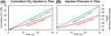 Figure 10. Results of the reference and variant injection scenarios showing (A) cumulative CO2 injected and (B) bottomhole injection pressure response for the 30-yr simulation time frame. vs = versus.
DISCUSSION
Offshore Storage Resource Classification
The regional- and local-scale offshore storage resources and estimated storable quantities reported in this study for the mid-Cretaceous (middle Cretaceous 1–3), Lower Cretaceous (Lower Cretaceous 1), and Jurassic (Upper Jurassic 1) intervals are described in terms of industry standards being developed by the SRMS through international collaboration between the Society of Petroleum Engineers and other CCS experts (Society of Petroleum Engineers, 2017). The SRMS is modeled after the widely used classification framework established by the Petroleum Resources Management System for the oil and gas industry to communicate project risk and commercial potential to investors and stakeholders (Society of Petroleum Engineers, 2018). As such, the SRMS is an important standard that was adopted in this project to classify and categorize the offshore storage resources based on uncertainty ranges and their changes of commerciality in the mid-Atlantic study area.
The results derived from static and dynamic assessment methods employed in this study are categorized as prospective storage resources (Society of Petroleum Engineers, 2017; US Department of Energy National Energy Technology Laboratory, 2017) (Figure 11). Prospective storage resource estimates do not account for regulatory issues or system-wide techno-economics of a CCS project. Regional estimates have been calculated stochastically and reported at the P10, P50, and P90 ranges to represent uncertainty in the estimated net connected pore volumes and account for an order of magnitude of potential error in the permeability values assigned to the storage zones of interest. Regional storage resources reported in this work can be classified at the play level in terms of project maturity (Figure 11). Local-scale storage resources estimated for the middle Cretaceous 3 injection zone using dynamic reservoir simulation require additional refinement to advance to the lead level. This could be accomplished via more sophisticated static and dynamic earth models to better characterize the geospatial variability of accessible pore volumes, reservoir injectivity, flow boundaries, and trapping mechanisms in the selected area.
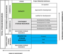 Figure 11. The framework used in this study for classification of offshore storage resources and their project maturity subclasses are based on the CO2 Storage Resources Management System (Society of Petroleum Engineers, 2017).
Offshore-Specific Storage Efficiency
Low (P10), median (P50), and high (P90) probability values were calculated for each storage efficiency parameter (equations 1, 2) to derive offshore-specific estimates of deep saline storage efficiency and facilitate comparison to regional-scale storage efficiency ranges reported for onshore deep saline formations. Using formation-specific well-log, core, and seismic data from the three offshore storage zones of interest, sandstone with gamma-ray values less than 75 gAPI was used to delineate reservoir intervals (i.e., sandstone) from nonreservoir intervals (i.e., shale), and permeability was used as a proxy to represent connected pore volumes. Minimum permeability cutoffs of greater than or equal to 10 md and greater than or equal to 100 md were applied, respectively, along with the gamma-ray cutoff to quantify the total and net effective pore volume available for CO2 storage. Table 3 shows storage efficiency probability values calculated for offshore deep saline formations in this study compared to those reported by DOE-NETL (e.g., Goodman et al., 2011). The displacement efficiency factors obtained in this study fall within the published range for onshore saline formations, with values between 7% and 24% reported for clastic lithologies by Goodman et al. (2011) and the International Energy Agency Greenhouse Gas Research and Development Programme (2009).
Figure 12 shows storage efficiency p values determined in this study compared to values reported for onshore deep saline formations in the fifth edition of the US DOE-NETL Carbon Storage Atlas (US Department of Energy National Energy Technology Laboratory, 2015). The higher efficiencies and larger range of p values from this study may reflect greater variation in sediment compaction and lithification in offshore environments, which could contribute to higher porosity and permeability relative to onshore basins. Offshore displacement efficiencies exhibit slightly higher P50 values and the same range as onshore formations.
 Figure 12. Median (50th percentile) storage efficiency values determined in this study compared to those reported by the US Department of Energy National Energy Technology Laboratory (2015) (DOE-NETL). Error bars represent the low (10th percentile) and high (90th percentile) values.
Regional Prospective Storage Resources
Regional prospective storage resources calculated for the three storage zones range from 37 to 403 Gt of CO2, with median P50 values of 148 Gt, 178 Gt, and 153 Gt calculated for the middle Cretaceous 1–3, Lower Cretaceous 1, and Upper Jurassic 1, respectively. In 2016, total CO2 emissions from power generation and industrial point sources in the eastern United States were approximately 0.15 Gt/yr (Battelle, 2018). Assuming CO2 emissions increase annually by an average of 6% (US Energy Information Administration, 2018), P10 values of 37 Gt (middle Cretaceous 1–3), 59 Gt (Lower Cretaceous 1), and 54 Gt (Upper Jurassic 1) suggest there is a high probability that each of the potential offshore storage zones has a CO2 storage resource greater than the cumulative 30-yr quantity of CO2 emitted (12.6 Gt) from the nearby point sources evaluated.
As previously mentioned, the regional-scale storage resource estimates reported in this study are classified at the play level for prospective storage resources, denoting initial preliminary results should be further refined to determine project feasibility and the chances of commercialization. Additional data and analysis are needed to reduce uncertainty and data gaps in each of the offshore mid-Atlantic subregions and better constrain the continuity and connectivity of reservoir pore volumes in selected area(s).
Local Prospective Storage Resources
Simplified dynamic injection and storage simulation were conducted to determine injection pressure constraints, provide local-scale CO2 storage resource estimates, and evaluate the feasibility of commercial-scale storage operations for a selected area of the mid-Atlantic offshore study region. Preliminary results from dynamic modeling suggest a single 51-m (167-ft)-thick injection zone in the middle Cretaceous 3 sandstone sequence alone could potentially store CO2 quantities greater than the annual and 30-yr cumulative CO2 emissions from one nearby power plant or industrial source along the eastern United States. As much as 51 Mt of CO2 was able to be injected and stored over 30 yr at the maximum allowable injection pressure determined by the fracture pressure gradient. For the reference injection scenario (1.5 Mt CO2/yr), 45 Mt of CO2 was stored over 30 yr while maintaining injection pressures below the maximum allowable injection pressure. These injection rates are approximately equivalent to or greater than the annual emission rates associated with 90% of the individual CO2 sources in the region (Battelle, 2018).
Net pay flags (gamma ray <75 gAPI, K ≥ 100 md, and thickness ≥6.1 m [≥20 ft]) were also observed in the middle Cretaceous 1, middle Cretaceous 2, Lower Cretaceous 1, and Upper Jurassic 1 zones within the selected area near the Great Stone Dome, with the middle Cretaceous 2 net pay flag exhibiting lateral and vertical continuity comparable to that observed at the top of the middle Cretaceous 3 reservoir selected for local-scale dynamic storage resource calculations (Figure 9). This suggests the stacked storage resources in the selected area could potentially accommodate commercial-scale CO2 quantities from more than one industrial CO2 source in the eastern United States. Results from the local-scale dynamic injection and storage simulation in this study are consistent with results of previous work that suggest large-scale CO2 storage is feasible in the offshore mid-Atlantic region (e.g., Slater et al., 2010; Brown et al., 2011; Midwest Regional Carbon Sequestration Partnership, 2011).
Although an injection rate of 1.5 Mt CO2/yr (reference scenario) was achieved without compromising formation integrity, dynamic simulation results for the more conservative 1.0 Mt CO2/yr injection scenario suggest injection at a lower rate for a longer period would enable the same ultimate amount of CO2 to be stored without the additional pressure buildup observed in the closed system for the reference injection scenario. It should also be noted that aside from the uplift and structural closure formed in Cretaceous-age strata above the Great Stone Dome, there were no geologic features identified in the selected area that are expected to act as lateral no-flow boundaries. Consequently, the potential pressure response during actual CO2 injection activities may be lower than those observed in the two injection scenarios modeled in the selected area.
In 2016, there were 39 power plants and 5 petroleum processing facilities with emissions greater than 1 Mt/yr in the eastern United States (Environmental Protection Agency, 2016). Annual CO2 emissions from power generation and industrial sources in the eastern United States were approximately 0.15 Gt in 2016, with CO2 emission expected to increase by an average of 6% annually (Environmental Protection Agency, 2016; Battelle, 2018; US Energy Information Administration, 2018). The P10 values of 37–59 Gt suggest a high probability that the offshore storage resources evaluated could accommodate commercial-scale storage of CO2 emitted from nearby point sources in the mid-Atlantic region for decades.
SUMMARY
Offshore CO2 storage resource estimates have been calculated to establish preliminary, screening-level constraints on the CO2 storage potential of mid-Atlantic offshore deep saline formations helping delineate and classify storage resources and their respective subclasses at the regional, subbasin, and local scales. Offshore storage resource estimates were based on comprehensive data integration methods that incorporated analysis of risk factors, data availability, and formation-specific storage efficiency calculations unique to offshore environments. Factors such as basin age and maturity and sediment lithification were used to establish screening criteria to identify offshore subregion(s) with suitable conditions for storage resource calculations. Core, log, and seismic data were compared, correlated, and processed to quantify and map petrophysical properties and pore volumes for three potential storage zones in middle–Lower Cretaceous and Upper Jurassic sandstone sequences, including portions of the offshore subsurface that had not been previously characterized for carbon storage.
As part of this effort, offshore-specific storage efficiency values were also determined from data available from the formations of interest in the study area and used as input in stochastic volumetric calculations for the regional grids. Resource estimates were refined at the local scale using dynamic reservoir simulation in a selected area of the northern Baltimore Canyon Trough (Figure 8). The selected area was identified on regional storage resource maps, exhibiting the highest estimated storage resource (≥2.4 Mt CO2/km2 [≥6.2 Mt CO2/mi2]) and relatively dense well data coverage (well spacing ≤5 km [≤3.1 mi]) observed within a 596 km2 (230 mi2) area.
Probability values ranging from 0.10 (low) to 0.58 (high) were derived for geologic storage efficiency terms using the combined net-to-total pore volume data set from the three offshore storage zones. The distribution of dynamic simulation results produced displacement efficiencies with a P10 of 0.09 and a P90 of 0.26. Regional prospective storage resources calculated for the three storage zones range from 37 to 403 Gt of CO2. Storage resource maps for all three storage zones show high estimated storage resource (P50 > 2.4 Mt CO2/km2) occurring in the northern Baltimore Canyon Trough near the Great Stone Dome structure (Figure 13). Simplified dynamic reservoir simulation performed for one 51-m (167-ft)-thick net reservoir interval within the middle Cretaceous 3 sequence near the Great Stone Dome suggests that approximately 45–51 Mt of CO2 could be stored over 30 yr via the specific single-well injection scenarios and pressure constraints evaluated.
 Figure 13. Map showing the well locations, three subregions, and Great Stone Dome outline alongside prospective storage resource estimates in megatonnes of CO2 per square kilometer for middle Cretaceous 1–3 (MK1-3) zone. CT = Connecticut; DE = Delaware; GRS = geodetic reference system; MA = Massachusetts; MD = Maryland; NAD83/UTM zone 19N = North American Datum 1983 Universal Transverse Mercator, zone 19 (northern hemisphere); NJ = New Jersey; NY = New York; P50 = 50th percentile; PA = Pennsylvania; RI = Rhode Island.
Additional subsurface data analysis using the newly inventoried, preserved, and digitized existing well data in the northern Baltimore Canyon Trough is needed to better characterize the geospatial variability of accessible pore volumes, reservoir injectivity, caprock and confining mechanisms, and potential contingent storage resources in the selected area near the Great Stone Dome. This could be accomplished through development of a more comprehensive, higher-resolution three-dimensional static earth model to better represent reservoir pore volumes and flow zone geometries and help refine dynamic storage simulation. Other key outcomes and findings are summarized as follows.
• Detailed characterization of key petrophysical properties (e.g., pore volume, permeability) for the three potential storage zones suggests targeted net reservoir intervals contain average porosities ranging from 21% to 29% and mean permeabilities ranging from 45 to 339 md. These values are within the range of porosities and permeabilities reported for other offshore reservoirs currently being used or evaluated for commercial-scale CO2 storage (Norwegian Petroleum Directorate, 2011, 2013; Treviño and Meckel, 2017).
• Offshore formation-specific probability ranges were determined for geologic and displacement efficiencies based on an integrated data set of regional core, log, seismic, and biostratigraphic data. The total storage efficiency of the combined Cretaceous–Jurassic interval of interest ranged from 0.01 to 0.11, with a P50 of 0.04.
• Both the regional static storage resource calculations and local-scale dynamic simulation suggest a high probability that the storage resources of the three storage zones evaluated could accommodate safe, long-term storage of CO2 from nearby industrial sources and power plants over commercial time scales.
REFERENCES CITED
Amato, R. V., and J. W. Bebout, eds., 1980, Geologic and operational summary, COST No. G-1 Well, Georges Bank Area, North Atlantic OCS: Reston, Virginia, US Geological Survey Open-File Report 80–268, 112 p., accessed January 27, 2016, https://pubs.usgs.gov/of/1980/0268/report.pdf.
Anthonsen, K. L., P. Aagaard, P. E. S. Bergmo, M. Erlström, J. I. Fareide, S. R. Gislason, G. M. Mortensen, and S. Ó. Snæbjörnsdottir, 2013, CO2 storage potential in the Nordic region: Energy Procedia, v. 37, p. 5080–5092, doi:10.1016/j.egypro.2013.06.421.
Bachu, S., D. Bonijoy, J. Bradshaw, R. Burruss, S. Holloway, N. P. Christensen, and O. M. Mathiassen, 2007, CO2 storage capacity estimation: Methodology and gaps: International Journal of Greenhouse Gas Control, v. 1, no. 4, p. 430–443, doi:10.1016/S1750-5836(07)00086-2.
Battelle, 2018, Mid-Atlantic U.S. offshore carbon storage resource assessment project: Final technical report: Columbus, Ohio, Battelle, 776 p., accessed November 19, 2019, https://edx.netl.doe.gov/dataset/mid-atlantic-final-technical-report.
Blondes, M. S., S. T. Brennan, M. D. Merrill, M. L. Buursink, P. D. Warwick, S. M. Cahan, and T. A. Cook, et al., 2013, National assessment of geologic carbon dioxide storage resources—Methodology implementation: Reston, Virginia, US Geological Survey Open-File Report 2013–1055, 26 p., accessed February 19, 2017, http://pubs.usgs.gov/of/2013/1055/.
Bradshaw, B. E., L. K. Spencer, A.-L. Lahtinen, K. Khider, D. J. Ryan, J. B. Colwell, and A. Chirinos, et al., 2011, An assessment of Queensland’s CO2 geological storage prospectivity—The Queensland CO2 geological storage atlas: Energy Procedia, v. 4, p. 4583–4590, doi:10.1016/j.egypro.2011.02.417.
Bradshaw, J., S. Bachu, D. Bonijoly, R. Burruss, S. Holloway, N. P. Christensen, and O. M. Mathiassen, 2007, CO2 storage capacity estimation: Issues and development of standards: International Journal of Greenhouse Gas Control, v. 1, no. 1, p. 62–68, doi:10.1016/S1750-5836(07)00027-8.
Brennan, S. T., R. C. Burruss, M. D. Merrill, P. A. Freeman, and L. F. Ruppert, 2010, A probabilistic assessment methodology for the evaluation of geologic carbon dioxide storage: Reston, Virginia, US Geological Survey Open-File Report 2010–1127, 31 p., accessed February 19, 2017, http://pubs.usgs.gov/of/2010/1127.
Brown, A., E. Berlin, R. Butsch, O. Senel, J. Mills, A. Harichandran, and J. Wang, 2011, Carbon capture and sequestration: Ascertaining CO2 storage potential, offshore New Jersey, USA: Offshore Technology Conference, Houston, Texas, May 2–5, 2011, OTC-21995-MS, 24 p., accessed January 29, 2018, https://www.onepetro.org/conference-paper/OTC-21995-MS.
Carbon Sequestration Leadership Forum, 2007, Estimation of CO2 storage capacity in geological media: Phase II final report from the task force for review and identification of standards for CO2 storage capacity estimation: Washington, DC, Carbon Sequestration Leadership Forum, 42 p., accessed January 13, 2016, https://pdfs.semanticscholar.org/0620/348ed0bdf3dd1ff9ef808acf852926425db1.pdf?_ga=2.114428679.1203726574.1562871677-1234669670.1561559897.
Carbon Sequestration Leadership Forum, 2008, Comparison between methodologies recommended for estimation of CO2 storage capacity in geological media: Phase III report from the CSLF task force on CO2 storage capacity estimation and the USDOE capacity and fairways subgroup of the regional carbon sequestration partnerships program, Washington, DC, Carbon Sequestration Leadership Forum, 17 p., accessed January 13, 2016, http://citeseerx.ist.psu.edu/viewdoc/download?doi=10.1.1.352.9809&rep=rep1&type=pdf.
Collins, D. J., J. Conrad, and C. Brown, 2017, Characterization of the Triassic Newark Basin of New York and New Jersey for geologic storage of carbon dioxide: Houston, Texas, Geostock Sandia, 1902 p., accessed November 15, 2019, doi:10.2172/1368193.
Craddock, W. H., M. D. Merrill, T. L. Roberts-Ashby, S. T. Brennan, M. L. Buursink, R. M. Drake, II, and P. D. Warwick, et al., 2018, Geologic framework for the national assessment of carbon dioxide storage resources—Atlantic coastal plain and eastern Mesozoic Rift Basins, in P. D. Warwick and M. D. Corum, eds., Geologic framework for the national assessment of carbon dioxide storage resources: Reston, Virginia, US Geological Survey Open-File Report 2012–1024, 32 p., accessed November 15, 2019, https://pubs.usgs.gov/of/2012/1024/n/ofr20121024n.pdf.
Cumming, L., N. Gupta, K. Miller, C. Lombardi, D. Goldberg, U. ten Brink, D. Schrag, D. Andreasen, and K. Carter, 2017, Mid-Atlantic U.S. offshore carbon storage resource assessment: Energy Procedia, v. 114, p. 4629–4636, doi:10.1016/j.egypro.2017.03.1590.
Degen, T., M. Sadki, E. Bron, U. König, and G. Nénert, 2014, The HighScore suite: Powder Diffraction, v. 29, Suppl. 2, p. S13–S18, doi:10.1017/S0885715614000840.
Duan, Z., and R. Sun, 2003, An improved model calculating CO2 solubility in pure water and aqueous NaCl solutions from 273 to 533 K and from 0 to 2000 bar: Chemical Geology, v. 193, no. 3–4, p. 257–271, doi:10.1016/S0009-2541(02)00263-2.
Environmental Protection Agency, 2016, Summary data collected by the Greenhouse Gas Reporting Program for 2016, accessed October 5, 2018, https://www.epa.gov/sites/production/files/2018-10/ghgp_data_2016_8_19_2018.xlsx.
Environmental Protection Agency, 2018, Facility level information on greenhouse gases tool (FLIGHT), 2018 greenhouse gas emissions from large facilities, accessed November 10, 2019, https://ghgdata.epa.gov/ghgp/main.do.
Erickson, S. N., and R. D. Jarrard, 1998, Velocity-porosity relationships for water-saturated siliciclastic sediments: Journal of Geophysical Research, v. 103, no. B12, p. 30385–30406, doi:10.1029/98JB02128.
Frailey, S. M., 2013, Estimating CO2 plume size: A correlation for site screening: International Journal of Greenhouse Gas Control, v. 13, p. 230–234, doi:10.1016/j.ijggc.2012.11.033.
Frailey, S. M., 2014, Corrigendum to “Estimating CO2 plume size: A correlation for site screening” [Int. J. Greenhouse Gas Control 13C (2013) 230–234]: International Journal of Greenhouse Gas Control, v. 21, p. 243, doi:10.1016/j.ijggc.2014.01.010.
Furre, A.-K., O. Eiken, H. Alnes, J. N. Vevatne, and A. F. Kiær, 2017, 20 years of monitoring CO2-injection at Sleipner: Energy Procedia, v. 114, p. 3916–3926, doi:10.1016/j.egypro.2017.03.1523.
Goodman, A., A. Hakala, G. Bromhal, D. Deel, T. Rodosta, S. Frailey, and M. Small, et al., 2011, U.S. DOE methodology for the development of geologic storage potential for carbon dioxide at the national and regional scale: International Journal of Greenhouse Gas Control, v. 5, no. 4, p. 952–965, doi:10.1016/j.ijggc.2011.03.010.
Goodman, A., S. Sanguinito, and J. S. Levine, 2016, Prospective CO2 saline resource estimation methodology: Refinement of existing US DOE-NETL methods based on data availability: International Journal of Greenhouse Gas Control, v. 54, p. 242–249, doi:10.1016/j.ijggc.2016.09.009.
Grow, J. A., and R. E. Sheridan, 1988, U.S. Atlantic Continental Margin; A typical Atlantic-type or passive continental margin, in R. E. Sheridan and J. A. Grow, eds., The Atlantic Continental Margin: Boulder, Colorado, Geological Society of America, v. 1–2, p. 1–7, doi:10.1130/DNAG-GNA-I2.1.
Hovorka, S., M. L. Romero, A. G. Warne, W. A. Ambrose, T. A. Tremblay, R. H. Treviño, and D. Sasson, 2013, Lower Potomac Group, CO2 brine database, accessed November 15, 2019, https://www.beg.utexas.edu/gccc/research/brine-main.
International Centre for Diffraction Data, 2018, PDF-4+ 2018, accessed February 5, 2018, http://www.icdd.com/pdf-4/.
International Energy Agency, 2017, Energy technology perspectives 2017: Catalysing energy technology transformations: Paris, International Energy Agency, 443 p., doi:10.1787/energy_tech-2017-en.
International Energy Agency Greenhouse Gas Research and Development Programme, 2009, Development of storage coefficients for CO2 storage in deep saline formations: Cheltenham, United Kingdom, International Energy Agency Greenhouse Gas Research and Development Programme Technical Study Report 2009/13, 118 p., accessed September 9, 2014, http://documents.ieaghg.org/index.php/s/YKm6B7zikUpPgGA/download?path=%2F2009%2FTechnical%20Reports&files=2009-13.pdf.
Jansa, L. F., and G. Pe-Piper, 1988, Middle Jurassic to Early Cretaceous igneous rocks along eastern North American continental margin: AAPG Bulletin, v. 72, no. 3, p. 347–366, doi:10.1306/703C8C27-1707-11D7-8645000102C1865D.
Kim, H., Y. H. Kim, S.-G. Kang, and Y.-G. Park, 2016, Development of environmental impact monitoring protocol for offshore carbon capture and storage (CCS): A biological perspective: Environmental Impact Assessment Review, v. 57, p. 139–150, doi:10.1016/j.eiar.2015.11.004.
Libby-French, J., 1984, Stratigraphic framework and petroleum potential of northeastern Baltimore Canyon Trough, mid-Atlantic Outer Continental Shelf: AAPG Bulletin, v. 68, no. 1, p. 50–73, doi:10.1306/AD460968-16F7-11D7-8645000102C1865D.
Mallick, S., 1995, Model-based inversion of amplitude-variations-with-offset data using a genetic algorithm: Geophysics, v. 60, no. 4, p. 939–954, doi:10.1190/1.1443860.
Midwest Regional Carbon Sequestration Partnership, 2011, Preliminary characterization of CO2 sequestration potential in New Jersey and the offshore coastal region: Ewing Township, New Jersey, New Jersey Geological Survey Final Report, 98 p., accessed February 16, 2015, https://irp-cdn.multiscreensite.com/5b322158/files/uploaded/njgs_carbon_sequestration_report_web.pdf.
Milligan, B., 2014, Planning for offshore CO2 storage: Law and policy in the United Kingdom: Marine Policy, v. 48, p. 162–171, doi:10.1016/j.marpol.2014.03.029.
Monastersky, R., 2013, Seabed scars raise questions over carbon-storage plan: Nature, v. 504, no. 7480, p. 339–340, doi:10.1038/504339a.
Norwegian Petroleum Directorate, 2011, CO2 storage atlas: Norwegian North Sea, accessed October 18, 2017, https://www.npd.no/globalassets/1-npd/publikasjoner/atlas-eng/co2-atlas-north-sea.pdf.
Norwegian Petroleum Directorate, 2013, CO2 storage atlas: Barents Sea, accessed October 18, 2017, https://www.npd.no/globalassets/1-npd/publikasjoner/atlas-eng/co2-atlas-barents-sea.pdf.
Poag, C. W., 1978, Stratigraphy of the Atlantic Continental Shelf and slope of the United States: Annual Review of Earth and Planetary Sciences, v. 6, no. 1, p. 251–280, doi:10.1146/annurev.ea.06.050178.001343.
Rietveld, H. M., 1967, Line profiles of neutron powder-diffraction peaks for structure refinement: Journal of Applied Crystallography, v. 22, p. 151–152, doi:10.1107/S0365110X67000234.
Rietveld, H. M., 1969, A profile refinement method for nuclear and magnetic structures: Journal of Applied Crystallography, v. 2, no. 2, p. 65–71, doi:10.1107/S0021889869006558.
Ringrose, P. S., 2018, The CCS hub in Norway: Some insights from 22 years of saline aquifer storage: Energy Procedia, v. 146, p. 166–172, doi:10.1016/j.egypro.2018.07.021.
Sanguinito, S., A. Goodman, and J. S. Levine, 2016, CO2-SCREEN user’s manual, accessed April 21, 2017, https://edx.netl.doe.gov/dataset/co2-screen-version-2-0.
Savva, D., T. Chrest, F. Saint-Ange, A. MacDonald, M. Luheshi, and L. Cuilhe, 2016, Structural impact of the Yarmouth Arch in the Central Atlantic opening and on the southwest Nova Scotian Margin architecture: AAPG Search and Discovery article 30481, accessed March 12, 2017, http://www.searchanddiscovery.com/documents/2016/30481savva/ndx_savva.pdf.
Schlee, J., 1980, Seismic stratigraphy of the Baltimore Canyon trough: Reston, Virginia, US Geological Survey Open-File Report 80–1079, 76 p., accessed June 1, 2018, https://pubs.usgs.gov/of/1980/1079/report.pdf.
Schlee, J., J. C. Behrendt, J. A. Grow, J. M. Robb, R. E. Mattick, P. T. Taylor, and B. J. Lawson, 1976, Regional geologic framework off northeastern United States: AAPG Bulletin, v. 60, no. 6, p. 926–951, doi:10.1306/C1EA35E1-16C9-11D7-8645000102C1865D.
Scholle, P. A., 1977, Geological studies on the COST No. B-2 well, U.S. Mid-Atlantic outer continental shelf area: Reston, Virginia, US Geological Survey Circular Series 750, 71 p., doi:10.3133/cir750.
Schrag, D. P., 2009, Storage of carbon dioxide in offshore sediments: Science, v. 325, no. 5948, p. 1658–1659, doi:10.1126/science.1175750.
Slater, B., A. Stolorow, and L. Smith, 2010, Potential for supercritical carbon sequestration in the Offshore Bedrock Formations of the Baltimore Canyon Trough: AAPG Search and Discovery article 80143, accessed November 6, 2011, http://www.searchanddiscovery.com/pdfz/documents/2011/80143slater/ndx_slater.pdf.html.
Slatt, R. M., ed., 2006, Stratigraphic reservoir characterization for petroleum geologists, geophysicists, and engineers: Oxford, United Kingdom, Handbook of Petroleum Exploration and Production 6, 478 p.
Smith, M., R. Amato, M. Furbush, D. Pert, M. Nelson, J. Hendrix, L. Tamm, G. Wood, and D. Shaw, 1976, Geological and operational summary, COST No. B-2 well, Baltimore Canyon trough area, mid-Atlantic OCS: Reston, Virginia, US Geological Survey Open-File Report 76–774, accessed January 27, 2016, https://pubs.er.usgs.gov/publication/ofr76774.
Society of Petroleum Engineers, 2017, CO2 storage resources management system, accessed January 30, 2018, 45 p., https://www.spe.org/industry/docs/SRMS.pdf.
Society of Petroleum Engineers, 2018, Petroleum resources management system, accessed January 30, 2018, 57 p., https://www.onepetro.org/download/general/SPE-194053-WP?id=general%2FSPE-194053-WP.
Szulczewski, M. L., C. W. MacMinn, H. J. Herzog, and R. Juanes, 2012, Lifetime of carbon capture and storage as a climate-change mitigation technology: Proceedings of the National Academy of Sciences of the United States of America, v. 109, no. 14, p. 5185–5189, doi:10.1073/pnas.1115347109.
Treviño, R. H., and T. A. Meckel, 2017, Geologic CO2 sequestration atlas of Miocene strata, offshore Texas state waters: Austin, Texas, Bureau of Economic Geology, 74 p., doi:10.23867/RI0283D.
US Department of Energy National Energy Technology Laboratory, 2008, 2008 Carbon sequestration atlas of the United States and Canada, 2nd ed.: Pittsburgh, Pennsylvania, National Energy Technology Laboratory, 140 p., accessed February 19, 2017, https://edx.netl.doe.gov/no/dataset/2008-carbon-storage-atlas-of-the-united-states-and-canada.
US Department of Energy National Energy Technology Laboratory, 2010, 2010 Carbon storage atlas of the United States and Canada, 3rd ed.: Pittsburgh, Pennsylvania, National Energy Technology Laboratory, 160 p., accessed February 19, 2017, https://edx.netl.doe.gov/dataset/2010-carbon-atlas-of-the-united-states-and-canada.
US Department of Energy National Energy Technology Laboratory, 2012, 2012 Carbon storage atlas of the United States and Canada, 4th ed.: Pittsburgh, Pennsylvania, National Energy Technology Laboratory, 128 p., accessed February 19, 2017, https://edx.netl.doe.gov/dataset/the-united-states-2012-carbon-utilization-and-storage-atlas.
US Department of Energy National Energy Technology Laboratory, 2015, Carbon storage atlas, 5th ed.: Pittsburgh, Pennsylvania, National Energy Technology Laboratory, 113 p., accessed February 19, 2017, https://www.netl.doe.gov/research/coal/carbon-storage/natcarb-atlas.
US Department of Energy National Energy Technology Laboratory, 2017, Best practices: Site screening, site selection, and site characterization for geologic storage projects: Pittsburgh, Pennsylvania, National Energy Technology Laboratory DOE/NETL-2017/1844, 119 p., accessed November 10, 2019, https://www.netl.doe.gov/sites/default/files/2018-10/BPM-SiteScreening.pdf.
US Energy Information Administration, 2018, Annual energy outlook 2018 with projections to 2050: Washington, DC, US Energy Information Administration Office of Energy Analysis, 146 p., accessed November 10, 2019, https://www.eia.gov/outlooks/aeo/pdf/AEO2018.pdf.
Vangkilde-Pedersen, T., K. Kirk, N. Smith, N. Maurand, A. Wojcicki, F. Neele, C. Hendriks, Y.-M. Le Nindre, and K. L. Anthonsen, et al., 2009, Assessing European capacity for geological storage of carbon dioxide: Copenhagen, Denmark, EU GeoCapacity Project No. SES6-518318 Final Report, accessed October 8, 2017, http://www.geology.cz/geocapacity/publications/D42%20GeoCapacity%20Final%20Report-red.pdf.
Zhou, Q., J. T. Birkholzer, C.-F. Tsang, and J. Rutqvist, 2008, A method for quick assessment of CO2 storage capacity in closed and semi-closed saline formations: International Journal of Greenhouse Gas Control, v. 2, no. 4, p. 626–639, doi:10.1016/j.ijggc.2008.02.004.
AUTHORS
Isis Fukai is a geoscientist with experience in geochemical and petrophysical analysis, carbon storage resource assessment, and techno-economic evaluation. She is currently a Ph.D. student in energy science and engineering at the University of Tennessee in Knoxville.
Laura Keister received her B.S. in earth sciences with a specialization in petroleum geology and geophysics from The Ohio State University. She is currently a geoscientist supporting carbon storage and enhanced oil recovery (EOR) projects in the Energy Division at Battelle. Her research is focused on geologic characterization, geochemical analysis, petrophysics, and storage resource assessments.
Priya Ravi Ganesh received her M.S. in petroleum and geosystems engineering from The University of Texas at Austin. Her core expertise includes reservoir fluid-flow modeling and analysis tasks to support geologic CO2 sequestration and incidental storage with CO2–EOR projects.
Lydia Cumming received her B.S. in geology from The Ohio State University. Her research career during her time at Battelle was focused on applying science to develop innovative, cost-effective solutions for large-scale environmental problems for business and government clients. Her current interests include geologic storage of CO2 for climate change mitigation.
Will Fortin works in marine seismology extracting quantifiable information from seismic data. He received his Ph.D. in geophysics from the University of Wyoming and is currently an associate research scientist at the LDEO. Will focuses on understanding risks facing humanity including greenhouse gas mitigation through basaltic carbon sequestration and natural hazards associated with submarine landslides.
Neeraj Gupta holds a Ph.D. in geological sciences (hydrogeology) from The Ohio State University, M.S. in geochemistry from The George Washington University, and M.Sc. and B.Sc. in geology from Panjab University, India. He has worked at Battelle for 27 years and is a senior research leader in the Energy Division. He leads several domestic and international programs in CO2 storage and EOR.
ACKNOWLEDGMENTS
This material is based on work supported by the Department of Energy under award number DE-FE0026087. The integration of geophysical data by Heather McCarren of Chevron, previously Battelle, is gratefully acknowledged. We thank our colleagues involved in data processing and analysis efforts at the state geological surveys of Delaware, Maryland, and Pennsylvania, the US Geological Survey, LDEO at Columbia University, and Rutgers University, as well as our colleagues involved in advisory and review efforts at Harvard University, the Texas Bureau of Economic Geology, and Virginia Department of Mines, Minerals and Energy.