About This Item
- Full TextFull Text(subscription required)
- Pay-Per-View PurchasePay-Per-View
Purchase Options Explain
Share This Item
The AAPG/Datapages Combined Publications Database
GCAGS Transactions
Abstract
Submarine Fan Deposition of the Woodbine-Eagle Ford Interval (Upper Cretaceous), Tyler County, Texas
Charles T. Siemers (1)
ABSTRACT
Production of gas and some condensate from fine-grained fractured sandstone of the Upper Cretaceous Woodbine-Eagle Ford interval at depths of 10,800 to 11,350 ft in central northern Tyler County, Texas, has provided the impetus for a detailed paleoenvironmental analysis of the geology in that area. The productive area (Sugar Creek Field) is located a short distance south of the Sabine Uplift, which was an active positive area previous to, during, and following Woodbine-Eagle Ford deposition, and is slightly down-dip from the Lower Cretaecous continental shelf edge as delineated by the Angelina-Caldwell flexure and the Edwards reef trend. The Woodbine-Eagle Ford interval (between the Buda Limestone below and Austin Chalk above) is 150-200 ft thick in the Sugar Creek Field area, but thins to less than 50 ft thick above the Edwards reef buildup, and northward toward the Sabine Uplift where it is missing. Southward (down-dip), the interval thickens to greater than 1500 ft within a distance of 15 miles.
The Woodbine-Eagle Ford interval in this down-dip position is a mud-dominated clastic wedge. Cores from seven wells in the Sugar Creek Field area and two down-dip wells were examined in detail. Dark gray, organic-rich, silty shale with thinly laminated to ripple-bedded siltstone beds and small siderite nodules comprise most (40% to greater than 80%) of the Woodbine-Eagle Ford interval and contain a microfauna (foraminifera) indicative of outer shelf to upper slope water depth. The reservoir sandstones occur as complex, single to multi-story bodies 15-40 ft thick and are composed of fine- to very fine-grained quartz arenites. As viewed in polished core slabs, the sandstones are mostly "massive-appearing" (without discernible sedimentary structures). Beds are characterized by very sharp (non-gradational) basal contacts (sandstone/shale) with abundant drag marks, flute casts and other sole markings, and by abrupt upper contacts with shale.
X-ray radiography of core slabs has revealed a multitude of sedimentary structures in the otherwise "massive-appearing" sandstones. Massive to laminated and cross-stratified sandstone is dominant, but ripple-stratification, soft-sediment-deformation, and scour features are also present. Burrows and bioturbation are common, but confined only to the upper parts of sandstone beds, which may be separated by thin (1-2 inch) shale beds. These sedimentary features and their positions within well-defined sandstone genetic units indicate rapid deposition of sand by low- to high-concentration submarine density (turbidity) currents and associated tractive currents. Mud deposition and burrowing of the upper parts of sand beds occurred during quiet periods between the sand pulses. Highly deformed siltstone intervals often are present below the sandstone bodies and indicate rapid loading by sand deposition and/or slumping on unstable slopes. A conglomeratic submarine debris-flow deposit is also well-displayed in one core.
Subsurface correlation and mapping of the discontinuous, lenticular, sandstone bodies indicate that they are best delineated as a series of coalescing, dip-oriented lobes. Deposition appears most likely to have been as prograding submarine fan lobes, with sediment being channeled from up-dip delta and near-shore deposits across a narrow shelf and through shelf-edge breaks and then dumped down slope. These basin-filling deposits prograded seaward until the sediment source was cut off and subsequent deposition of the Austin Chalk occurred. Although a major erosional unconformity exists above the Woodbine to the north, no such unconformity can be documented above the down-dip Woodbine-Eagle Ford interval in Tyler County.
INTRODUCTION
The most prolific oil and gas stratigraphic interval in Northeast Texas has been the Upper Cretaceous Woodbine Group. Since the first Woodbine oil discovery at a depth of approximately 3100 ft at Mexia in October 1920, subsequent discovery at Boggy Creek in March 1927, and discovery of the giant East Texas Field in 1931, (Alexander, 1951), the Woodbine has been one of the most sought-after hydrocarbon-productive intervals in East Texas. Discovery and development of Woodbine production in the East Texas embayment area has been mostly at depths of 3,000-6,000 ft north of the Angelina-Caldwell monoclinal flexure (and Edwards "reef trend" which parallels approximately the Angelina-Caldwell flexure, Fig. 1). Discovery and development of Woodbine gas over the past few years in Polk and Tyler counties, south of the Angelina-Caldwell flexure, has been at depths of 10,000 to greater than 15,000 ft. These two areas can be referred to informally as the "up-dip" and "down-dip" areas of the Woodbine interval in East Texas. Since the Angelina-Caldwell flexure and Edwards reef trend are regarded as marking the seaward edge of the Late Cretaceous continental shelf and the beginning of the continental slope (Stehli et al., 1972), the "up-dip" Woodbine represents deposition north of the shelf break and "down-dip" Woodbine represents deposition south of the shelf break.
The depositional systems of the up-dip Woodbine have been rather well documented over the past 20-30 years. Oliver (1971) combined consideration of previous Woodbine study with his examination of Woodbine outcrops in northeastern Texas and southeastern Oklahoma with study of subsurface wire-line logs, cuttings and cores in northeast Texas to present an up-to-date synthesis of the depositional systems of the up-dip Woodbine. He represents that system as one that changes progressively from a southwestward flowing, fluvial coastal plain deposition in the northeastern most part of Texas, to delta plain and to nearshore marine and shallow marine prodelta shelf deposition in a southward and southwestward direction (Oliver, 1971, fig. 3 and 11). The down-dip Woodbine is a different story. Deep (greater than 10,000 ft) drilling south of the Angelina-Caldwell flexure (and the Edwards reef trend) has encountered a Woodbine lithologic sequence and depositional system which is considerably different from that of the up-dip Woodbine. The character and
End_Page 493------------------------
FIGURE 1. Index map of northeast Texas showing major structural features and position of Woodbine Formation outcrop. Modified from Oliver (1971), Nichols (1964), and Granata (1963).
End_Page 494------------------------
relative positions of the Sabine Uplift and Late Cretaceous continental shelf/slope break were dominant tectonic elements controlling Woodbine deposition in the East Texas counties of Polk, Tyler, Jasper and Newton.
The purpose of this paper is to describe in detail the stratigraphic and sedimentologic character of the Woodbine-Eagle Ford interval in Tyler County, and to present an interpretation of the depositional system of the down-dip Woodbine in that area. The area of detailed study is illustrated by Figures 1 and 5. Specific attention has been given to the Woodbine-Eagle Ford interval in the Sugar Creek Field area of central northern Tyler County (Fig. 8 and 9). The most significant data, relative to subsequent conclusions, has been obtained through careful examination of cores. A "process approach" was utilized throughout for interpretation of core sequences; that is, sedimentary rock sequences were examined bed by bed for texture, composition, physical and biogenic sedimentary structures, and bed-contact relationships, and then interpreted as to most probable specific sedimentary processes responsible for their formation. The recognition of vertical genetic sedimentation unit sequences was a second-order observation. A depositional model was generated by incorporation of: 1) inferred processes responsible for the generation of genetic sedimentation units and vertical lithologic sequence, 2) sedimentary body geometry as derived from subsurface core and log correlations, 3) consideration of regional tectonic elements and known sedimentation patterns, 4) local paleogeographic and paleotopographic setting as determined by structure contour and isopach maps, and 5) paleoecological inferences from examination of foraminiferal microfauna.
Stratigraphic Terminology
Stratigraphic terminology for the Woodbine and Eagle Ford intervals is extremely complex, owing mainly to: 1) these strata have been the subject of numerous studies over the past 50-100 years, 2) the units are well displayed in outcrop as well as by a vast amount of subsurface well-control, and 3) the Woodbine-Eagle Ford interval displays a varied and complex lithofacies pattern throughout East Texas. Most of the terminology which has been generated for the Woodbine-Eagle Ford interval refers to its up-dip portion. A few of the more common terms are listed in Figure 2. Since this study deals almost entirely with the sedimentology and paleoenvironments of the down-dip Woodbine-Eagle Ford, a comprehensive review of stratigraphic terminology is far beyond the scope of this paper. The interested reader is referred to Adkins (1933) who made a survey of pre-1932 published Woodbine work and to Dodge (1969) who updated that survey. Other very useful stratigraphic papers include Bailey, Evans and Adkins (1945), Hazzard, Blanpied and Spooner (1945), Lozo (1951), Adkins and Lozo (1951), and Granata (1963).
In this study the term "Woodbine-Eagle Ford" is used to refer to strata of the subsurface in Tyler County which lie between the Buda Limestone below and the Rapides Shales and Austin Chalk above. Both contacts are transitional but rather abrupt, and are easily picked in cores and on wire-line logs. The copper-colored Maness Shale, which is a recognized unit between the Buda and Woodbine in the up-dip subsurface (Lozo, 1951), is not recognized in the Tyler County cores. A thin (15-20 ft) shale interval immediately below the Austin Chalk is recognized by some geologists working with logs of the downdip Woodbine-Eagle Ford and is referred to as the Rapides Shale. Forgotson (1958) considered such a shale unit to belong with the Austin Chalk. Such a unit is not distinctive in cores, but has been recognized on logs. The character of these units, their contact relationships and paleoenvironmental implications are discussed at length later in this paper.
Although the Woodbine and Eagle Ford stratigraphic units are rather easily delineated in the up-dip area, no such distinction can be made in the study area of this report. Shale commonly is the dominant lithology occurring between the Buda and Austin carbonate units. Presumably, that shale-dominated interval represents much of the time of both Woodbine and Eagle Ford deposition. Sandstone units are discontinuous within this interval, and
FIGURE 2. Stratigraphic terminology of upper Comanchean and Gulfian strata of northeast Texas. Modified from Nichols (1964).
End_Page 495------------------------
when sandstone units are present, shale below and above are similar lithologically and paleontologically. It does not make sense to refer to sandstone units, wherever they occur, as Woodbine and to the shales above such sandstones as Eagle Ford. Therefore, since the lithologic sequence between the Buda and Austin cannot be correlated consistently with either the Woodbine or the Eagle Ford groups, and since the interval may actually represent both Woodbine and Eagle Ford deposition (of the up-dip area), it is referred to herein as Woodbine-Eagle Ford.
Several authors (i.e., Lozo, 1951, Adkins and Lozo, 1951; Oliver, 1971; Stehli et al, 1972) have recognized that the Woodbine of the up-dip area changes southward from a sand-dominated unit to a shale-dominated unit. Where this occurs the shale is called the Pepper Shale. Adkins and Lozo (1951, p. 113) supposed that the Pepper Shale is a southward continuation of the upper Woodbine group. Oliver (1971) illustrates the Pepper Shale as a marine shelf depositional facies of the Woodbine seaward of his Freestone Delta System. Within this framework of existing stratigraphic terms, it might be preferable to use the term Pepper Shale for the lithologic sequence between the Buda and Austin in Tyler County.
It is important to recognize that the Woodbine of East Texas correlates stratigraphically with the Tuscaloosa Formation of Louisiana, Arkansas. Mississippi and Alabama. Granata (1963) discussed the Woodbine-Tuscaloosa relationship in some detail. It should be emphasized, however, that although the Woodbine and Tuscaloosa may be lithostratigraphic equivalents, they may not represent exactly the same depositional system. Major changes in Late Cretaceous source areas and tectonic elements undoubtedly have resulted in significant variation in depositional systems of the Late Cretaceous from East Texas eastward along the Gulf Coast.
Tectonic Elements
The major tectonic elements of Northeast Texas are delineated in general in Figure 1. The most important elements affecting Woodbine-Eagle Ford deposition are: 1) the position of the Late Cretaceous outer continental shelf/upper slope/break, indicated by the Angelina-Caldwell flexure (and Edwards reef trend), and 2) the Sabine Uplift.
The Angelina-Caldwell flexure is a southward-plunging monocline which forms the southern termination of the East Texas embayment and which coincides, approximately, with a marked seaward thickening of the overlying Paleocene sedimentary prism. Stehli, et al. (1972), noted that Cretaceous microfaunal planktonic/benthonic ratios indicate that the Angelina-Caldwell flexure marks the seaward edge of the Late Cretaceous continental shelf, and the beginning of the continental slope. The Late Cretaceous shelf edge also is delineated by reef-like buildups
FIGURE 3. Diagramatic cross-section of Lower Cretaceous strata in the Texas and Louisiana Gulf Coast showing geometric relationships of shelf-edge barrier reefs. Modified from W. Feather Wilson in Hendricks and Wilson (1967).
End_Page 496------------------------
in the Early Cretaceous (Comanchean). The Edwards reef trend, which has been traced along the Louisiana and Texas Gulf Coast area and into Mexico, appears to best mark the most exact position of the outer shelf edge prior to, and during Woodbine-Eagle Ford deposition in Tyler County. The general positions of the Edwards, Sligo and other Early Cretaceous reef build-ups in the Gulf Coast area are indicated in Figure 3. As-should be expected, deposition of Woodbine-Eagle Ford sediments south of the shelf break was considerably different from that to the north.
The Sabine Uplift was an important tectonic feature during Woodbine-Eagle Ford time. Granata (1963), presented a comprehensive study of the Sabine tectonic element. He stated (p. 64-65) that the Sabine area was a positive feature during early Woodbine time, probably received sediments in late Woodbine, and then presumably became progressively more positive at the close of Woodbine time, culminating in the removal by erosion of the thin Woodbine and Tuscaloosa sediments which had been deposited over the structurally-higher part of the Sabine Uplift. Eagle Ford sediments show complex relationships around the Sabine Uplift, indicating a shift of the axis of uplift. Erosional off-laps of Eagle Ford sediments occur on the west flank of the uplift, but on-lap and over-lap of Eagle Ford sediment on the Tuscaloosa occur along the east flank of the uplift, indicating a westward shift of the axis of uplift. The general position of the Sabine Uplift during Woodbine-Eagle Ford time is illustrated in Figure 4 by the isopach map of the interval between the base of the Austin Chalk and the top of the Buda Limestone. Note the asymmetry of the uplift.
The important consequence of the relative positions of the southern edge of the Sabine Uplift and the Edwards reef trend, which marks the continental shelf break, is that the Late Cretaceous continental shelf in the Tyler County area was relatively quite narrow. The significance of such a narrow shelf will be re-emphasized in a later portion of this paper, following description and interpretation of the down-dip Woodbine-Eagle Ford interval in Tyler County.
Methodology
The principal strength of this study has been the detailed examination of full-diameter cores. The paleoenvironmental determinations presented herein would not have been possible without such core control. Wells from which cores were examined are indicated in Figure 5. Table 1 lists the cored intervals and their principle features. Most cores are from well in the Sugar Creek Field area; however, two down-dip wells (Delta, Carter No. 1 and Delta, Carter No. 2) provided cores of considerable interest and significance. All cores were slabbed, polished on a lap, and photographed prior to megascopic examination. Core condition varied considerably. The most complete core intervals are those of the Cities Service, Sutton B-1 and Cities Service, McHard A-1 wells. The author directly supervised and participated in the acquisition of those cores at the well site, closely supervised handling by a commercial core analysis laboratory, and personally transported them to the Cities Service Research Center for geological analyses. As a result of such care, the six cores from the McHard A-1 well (186 ft cored) represent a near-complete (98%) sequence through the entire Woodbine-Eagle Ford, including the lower several feet of the Austin Chalk and upper 17 feet of the Buda Limestone. The 126 ft of core from the Sutton B-1 well (three cores) contains all of the sandstone units and most of the Woodbine-Eagle Ford in that well, including the lower foot of the Austin Chalk. All important lithologic contacts are preserved, and the continuous shale and siltstone intervals above and below the sandstone units provide extremely valuable information for paleoenvironmental interpretation.
Because the majority of sandstone in the Sutton B-1 and McHard A-1 wells are massive-appearing, even on a slabbed and polished surface, the entire sandstone interval of each core was X-rayed. The core was cut into uniformly thick (3/8 to 1/2 inch) slabs, polished on both sides and X-rayed using a commercially available industrial instrument. Positive contact radiographic prints were also made from the X-ray radiograph negative. Such radiograph prints could then be used to more effectively analyze the exact nature of the physical and biological sedimentary structures and to reconstruct genetic sedimentation units within the otherwise "massive" sandstone bodies.
Core material (sandstone, shale, siltstone, limestone) also has been analyzed in thin section for composition and textures and by X-ray diffraction for clay mineral composition. Such petrographic data have been correlated with standard reservoir property determinations of porosity and permeability. Shales and some sandstones have been examined for microfauna, and those observations have provided critical paleoecological data. The abundance and character of organic carbon and kerogen, and their thermal maturity has been analyzed. In addition, the use of wire-line logs, dipmeter logs, including Schlumberger's Geo-Dip plot, have been utilized to analyze the Woodbine-Eagle Ford lithologic sequence.
GENERAL SUBSURFACE GEOLOGY OF WOODBINE-EAGLE FORD INTERVAL, TYLER COUNTY
Most of the wells which have penetrated the Woodbine-Eagle Ford in Tyler County, and immediately adjacent part of Jasper County, are indicated in Figure 5. Except for the Sugar Creek Field area in the central northern part of Tyler County, well control is sparse, and, for that reason, thicknesses of the Woodbine-Eagle Ford are indicated for each well penetrating the Buda Limestone, but isopachs were not mapped over the entire study area. Figures 6 and 7 illustrate, respectively, the mapped character of the Woodbine-Eagle Ford interval thickness and the subsurface structure in the Sugar Creek Field area. Note the approximate position of the Edwards reef trend through the field (Fig. 5, 6 and 7) and the slight steepening there of the gulfward-plunging structural ramp (Fig. 7).
The Woodbine-Eagle Ford interval in this area displays a spectacularly southward-thickening clastic wedge. The interval is less than 50 ft thick a short distance north of the Edwards reef trend, 100-200 ft thick in the productive area of Sugar Creek Field (Fig. 6) and thickens to more than 1,500 ft about 15 miles south of the Sugar Creek area (Fig. 5). The wedge is displayed in the subsurface log cross-section of Figure 8, and seismic section of Figure 9,
End_Page 497------------------------
FIGURE 4. Isopach map of the Woodbine-Eagle Ford interval (base of Austin Chalk to top of Comanchean) in northeast Texas and northwest Louisiana. Contour interval is 100 ft. Modified from Granata (1963)
End_Page 498------------------------
FIGURE 5. (Above) Index map of northern Tyler County and parts of adjacent counties showing wells which have penetrated to the Woodbine-Eagle Ford. The area of Sugar Creek Field is outlined and shown in greater detail, with well names, in Figures 6 and 7. Note the position of the Edwards reef trend. Total depth and thickness of the Woodbine-Eagle Ford interval (in parentheses) are included with well names. The line of the north-south cross-section of Figure 8 is indicated from the C & K Kirby #1 well to the Humble Howell #1 well. Note the location of wells from which Woodbine-Eagle Ford cores were obtained.
TABLE 1. (Left) List of Woodbine-Eagle Ford cores observed from the wells in Tyler County, Texas. See Figures 5-7 for location of wells.
End_Page 499------------------------
FIGURE 6. Isopach map of the Woodbine-Eagle Ford interval (base of Austin Chalk to top of Buda Limestone) in the area of Sugar Creek Field, central-northern Tyler County. The location of this map area is shown in Figure 5. Modified from working map prepared by Michael Ardeel and Kathy Barrie.
FIGURE 7. Structure map of the base of the Austin Chalk in the area of Sugar Creek Field, central-northern Tyler County. The location of this map area is shown in Figure 5. Modified from working map prepared by Michael Ardeel and Robert Hunt.
End_Page 500------------------------
FIGURE 8. North-south dip-section of Upper Cretaceous in Tyler County. Note the dramatic down-dip thickening of the mud-dominated Woodbine-Eagle Ford clastic wedge south of the Edwards reef trend. Position of cross-section is shown in Figure 5. Modified from working log section prepared by Kathy Barrie.
 FIGURE 9. [Grey Scale] Seismic section and sketch showing Woodbine-Eagle Ford down-dip clastic wedge in East Texas area. The positions of the Austin Chalk and Buda Limestone reflectors and the Edwards and Sligo reef build-ups are indicated. Also note the inclined reflectors within the mud-dominated Woodbine-Eagle Ford clastic wedge, indicating progradational surfaces. Modified from Sheriff (1976, fig. 10).
End_Page 501------------------------
and appears to have its apex at the Edward reef build-up. Note in the log cross-section that the Woodbine-Eagle Ford interval is dominantly shale. A few thin sandstone units are discernible in the lower parts of the interval in the Delta, Carter No. 1 and No. 2 wells, and in the Humble, Howell No. 1 well. The Hunt, Tapscott well occurs approximately along strike with gas-productive wells in Sugar Creek, but contains only a few thin sandstone beds and is not productive.
The seismic section shown in Figure 9 is reproduced from an article by Sheriff (1976, p. 540) and displays the typical configuration of the down-dip Woodbine-Eagle Ford in East Texas. Notable features include: 1) Edwards reef, 2) thin rather uniform Woodbine-Eagle Ford north of the Edwards reef, 3) down-dip thickening clastic wedge south of the Edwards reef, 4) inclined reflectors within the Woodbine-Eagle Ford interval, and 5) probable position of Sligo reef buildup. The inclined surfaces within the Woodbine-Eagle Ford interval probably represent slope surfaces of the prograding clastic wedge.
The general log character and lateral and vertical distribution of Woodbine-Eagle Ford sandstone bodies in the Sugar Creek Field area are shown in Figure 10. Significant characteristics include: 1) sandstone bodies may be rather simple or multistoried, 2) sandstone units may occur at any position vertically within the Woodbine-Eagle Ford interval, 3) individual sandstone units cannot easily be correlated from well to well along strike and appear to be quite discontinuous lens-shaped bodies in the strike direction, and 4) the best correlation occurs in a down-dip direction (e.g., ARCO, Humble #1 to Davidson, Neyland #1 correlation). The better-developed, more continuous sandstone units have been labeled from "A" for the lowest unit to "H" for the highest (Fig. 10). When sandstone units occur at about the same level, but are not connected, they have been given the same letter designation but differentiated by a prime notation (e.g., D and D , F and F).
In the Sugar Creek Field area, it is important to note that sandstone distribution and gas production correspond closely to the position of the Edwards reef. Three wells just north of the reef edge (C & K, Kirby No. 1, C & K, Howell No. 1-A and Cities Service, Longbell No. 1) reveal a thin Woodbine-Eagle Ford interval (50 ft, 95 ft and 70 ft respectively) composed entirely of silty and sandy shale. As shown in Figure 10, the interval thickens to 100-200 feet just south of the reef trend and contains relatively thick gas-productive sandstone bodies.
FORAMINIFERAL PALEOECOLOGY
Analysis of the foraminiferal content of Woodbine-Eagle Ford cuttings and core chips of several Tyler County wells has been made by John Etter of Cities Service Research. Shale samples from throughout the Woodbine-Eagle Ford interval (below, above and within the major sandstone units) and a few sandstone chips were examined. In general, the microfauna displays relatively low diversity, dominated by planktonic forms, which may be present in great abundance in some core shale samples. Foraminifera are most abundant in the shale interval above the sandstone units, but also occur in the thin shale
FIGURE 10. Fence diagram of Woodbine-Eagle Ford interval in the Sugar Creek Field area of central-northern Tyler County. The major sandstone bodies are indicated by the patterned areas labeled A-H from the base upward. Where sandstone bodies occur at the same level, but are not connected along the strike section, they are differentiated by a prime notation (e.g., D and D). Note the discontinuous lens shape of the sandstone bodies along strike within the mud (shale) interval. The best correlation is that in a dip direction from the ARCO Humble well to the Davidson, Neyland #1 well. Modified from diagram by Kathy Barrie.
End_Page 502------------------------
beds within the major sandstone units. Identifications have been made on the commonest forms and include the planktonic forms Globotruncana sp. and Globotruncana cf. G. marginata, Gumbelina inflata and G. moremani, Globigerina cf. G. planispira, Hedbergella planispira and Hastigerinella moremani. The distinctive bottom-dwelling species Planulina eaglefordensis also is commonly present and abundant in some samples. The large, robust arenaceous benthonic form Bathysiphon sp. also is present in a few shale samples. A few siltstone and sand-stone samples were crushed and examined for foraminifera and were found to contain specimens of Amobaculites sp. and several other, indeterminate, arenaceous forms.
The low faunal diversity with abundant planktonic forms and the relatively deep-water benthonic form Planulina eaglefordensis indicate that the fine-grained sediments of the Woodbine-Eagle Ford in Tyler County were deposited in an open marine outer-shelf to upper-slope environmental setting. Bathysiphon sp. is a benthonic form characteristic of deeper waters on the continental slope, and its presence indicates an even deeper-water setting. Of considerable additional interest is the abundance of nearshore-marine arenaceous forms in the sandstone units. In a later part of this paper, the overall significance of this is discussed in light of other lithologic observations and general tectonic setting of Woodbine-Eagle Ford deposition in the Tyler County area.
GENERAL PETROGRAPHY OF THE WOODBINE-EAGLE FORD AND VERTICALLY ADJACENT UNITS
Significant lithologic units and contact relationships observed in cores include: 1) Buda Limestone, 2) contact of Buda Limestone and overlying shale of the Woodbine-Eagle Ford, 3) Woodbine-Eagle Ford lithologies (listed below) and their contact relationships, 4) Rapides Shale, 5) contact of Rapides Shale and upper part of Woodbine-Eagle Ford, 6) Austin Chalk, and 7) contact of Rapides Shale and overlying Austin Chalk. The main lithofacies of the Woodbine-Eagle Ford include: 1) silty shale containing such features as thin sandstone and siltstone beds, siderite nodules, intervals with abundant shell debris, bioturbated intervals and contorted and deformed intervals, 2) highly contorted (soft-sediment-deformed), sandy and shaly siltstone units, and 3) thick massive-appearing sand-stone units. All of these units and contacts, except the sandstone, are described in this section; sandstones are discussed in detail in a following section. The general lithologic character of these units, as observed in excellent continuous cores and wire logs of the Cities Service, Sutton B-1 and McHard A-1 wells, is displayed in Figures 11-14.
Buda Limestone (Upper Part) and Upper Contact
The first distinctive carbonate unit occurring below the terrigenous clastics of the Woodbine-Eagle Ford interval in Tyler County is referred to as the Buda Limestone. The Buda has been observed in three cores from the Sugar Creek Field area (Cities Service, McHard A-1, C & K, Kirby No. 1, and Cities Service, Long Bell No. 1) and is easily differentiated from the Woodbine on wire-line logs (e.g., see Figures 13 and 14). The contact between the Woodbine and Buda appears to be very sharp on the wire-line logs and has been interpreted by some as an erosional unconformity; however, when viewed in cores and thin sections, the contact is actually transitional over an interval of at least 2 to 5 feet. The sedimentological character of the Buda, and its contact with the Woodbine are critical observations relevant to the understanding of the paleoenvironmental depositional character of Woodbine-Eagle Ford interval.
The Buda Limestone displays essentially the same lithologic character as observed throughout its upper 17 feet in the Cities Service, McHard A-1 core (Fig. 12), upper 37 feet in the C & K, Kirby No. 1 core, and upper 32 feet in the Cities Service, Long Bell No. 1 core. The limestone is mainly a highly bioturbated calcisphere- and echinoid-bearing biomicrite (classification scheme of Folk, 1959) or wackestone (classification scheme of Dunham, 1962). The limestone is slightly shaly but characterized mainly in cores (Fig. 15; interval A) by its bioturbated character. It is medium light gray (N6; Rock Color Chart of Goddard, 1963) to medium dark gray (N4), being darker where more shaly with terrigenous clay and silt material. A few core pieces of the very dense, well-indurated, brittle limestone displayed vertical fractures; however, most (>90%) of the core does not contain fractures. Only a vague subhorizontal bedding fabric remains as a result of the intense bioturbation. No discernible trace fossil types have been recognized except for a few vermiform structures marked by darker clay-fill in light gray carbonate mud. Minor amounts of disseminated pyrite may concentrate in burrow structures. In thin section (Fig. 16 A, B) the Buda is characterized by the abundance of calcispheres in a slightly recrystallized lime mud matrix. The rock is generally 50-60% micrite (or microspar), 30-40% calcispheres, 3-6% globigerinid foraminifera, and 3-8% quartz silt. Minor amounts of sparry calcite may be present, apparently controlled by burrowing, and secondary pyrite may be present up to 5-10% of the rock, as finely disseminated cubic crystals or as partial replacement of small burrow-like structures. The amount of quartz silt appears to increase in the upper part of the limestone unit. The volume of terrigenous clay is difficult to determine in thin section and has not been measured, but may be appreciable in some of the darker zones of the limestone.
The calcispheres of the Buda Limestone core were studied in this section and by Scanning Electron Microscopy by Mark Longman of Cities Service Research (personal communication, June, 1977) who indicated the following characteristics. The calcispheres typically are about 60 microns in diameter and consist of a two-layered, non-perforate, reticular calcareous wall, and thus are not from foraminifera, but are instead the problematic genus Pithonella (see Banner, 1972; Bein and Reiss, 1976). Pithonella is a widespread Cretaceous genus of uncertain affinities but most probably was some sort of algal structure and very likely was planktonic.
Based on the general textural and compositional character of the Buda Limestone, the character of its contact with the overlying Woodbine, and the inferred depositional character of the Woodbine-Eagle Ford system, it is most likely that the Buda Limestone represents slow carbonate mud deposition in a deep quiet-water setting (slope or deeper) in which calcispheres could slowly accumulate
End_Page 503------------------------
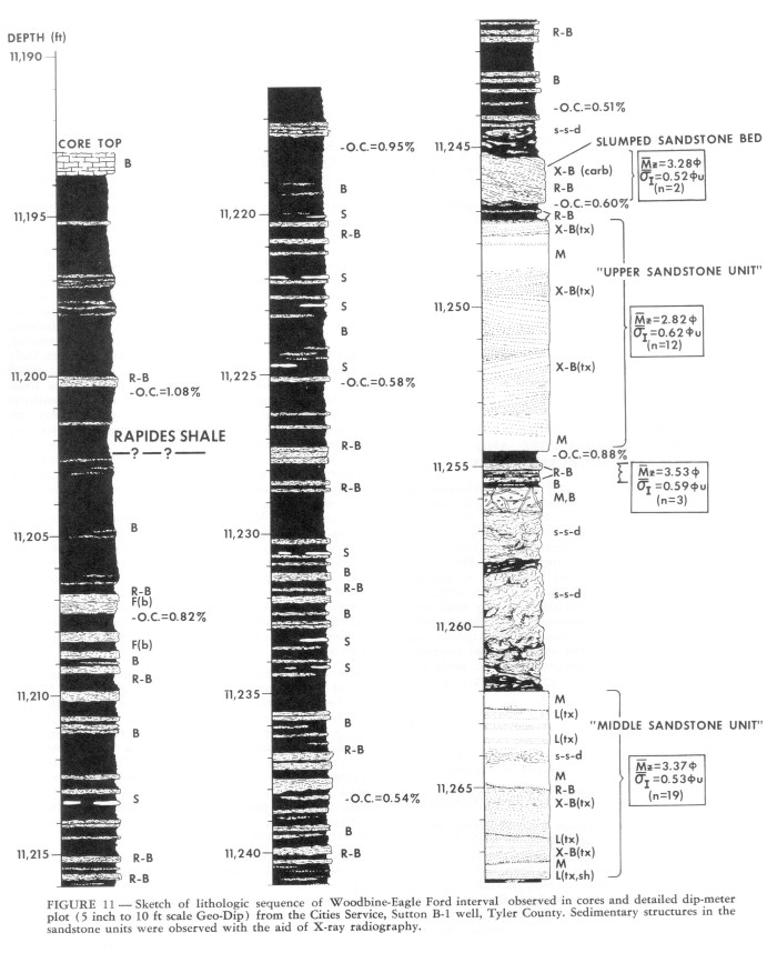 FIGURE 11. [Grey Scale] Sketch of lithologic sequence of Woodbine-Eagle Ford interval observed in cores and detailed dip-meter plot (5 inch to 10 ft scale Geo-Dip) from the Cities Service, Sutton B-1 well, Tyler County. Sedimentary structures in the sandstone units were observed with the aid of X-ray radiography.
End_Page 504------------------------
 FIGURE 11. [Grey Scale] See caption on page 504.
End_Page 505------------------------
 FIGURE 12. [Grey Scale] Sketch of lithologic sequence of Woodbine-Eagle Ford interval (including lower part of Austin Chalk and upper part of Buda Limestone) observed in cores and dip-meter plot (5 inch to 10 ft scale Geo-Dip) from the Cities Service, McHard A-1 well, Tyler County. Sedimentary structures in sandstone units were observed with the aid of X-ray radiography. See Figure 11 for explanation of symbols
End_Page 506------------------------
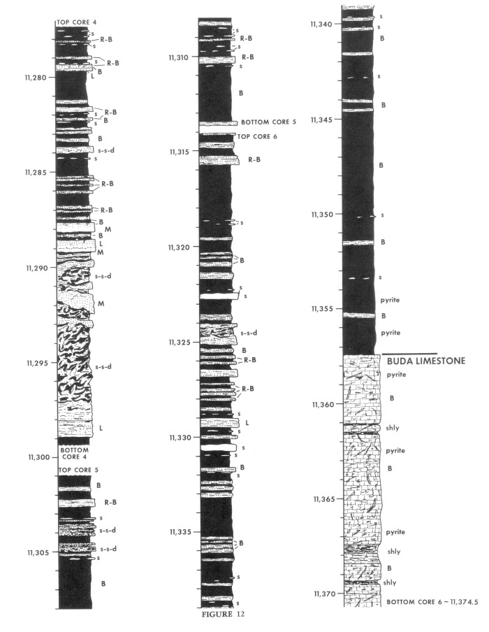 FIGURE 12. [Grey Scale] See caption on page 506.
End_Page 507------------------------
and echinoids and soft-bodied organisms could thoroughly bioturbate the bottom. Such deposition eventually was interrupted by the increased influx of terrigenous mud now represented by the lower part of the Woodbine.
The character of the Buda/Woodbine contact already has been alluded to above. The contact is relatively sharp on wire-line logs (especially resistivity logs), but cores reveal a moderately distinct but transitional contact over a distance of about 2 feet to more than 5 feet. When the core and logs are compared, the Buda/Woodbine contact (as defined by the log) can be narrowed down to within a few inches in the core. Below that point, the lithology is medium-gray, dense, bioturbated limestone. For a few feet above the contact point, the lithology is a moderately fissile, dark-gray, calcareous shale with vaguely interbedded clayey limestone. The transitional nature of the contact is documented by the gradual increase of quartz silt toward the top of the Buda and the persistence of calcispheres well up into the lower shale of the Woodbine-Eagle Ford. Abundant calcispheres were observed at least 2 feet above the "contact" in the Cities Service, McHard A-1 well (Fig. 16D) and over 5 feet above the "contact" in the Cities Service, Long Bell No. 1 well. The significance of this contact will be re-emphasized later in the discussion of this report.
Woodbine-Eagle Ford Shale and Deformed Siltstone
As indicated above, and illustrated in Figures 11 and 12, the Woodbine-Eagle Ford interval consists of three main lithofacies: 1) silty shale of highly variable character, 2) highly contorted sandy and shaly siltstone, and 3) massive-appearing sandstone. The shales and deformed siltstone intervals are described and discussed in this section. A significant feature of the Woodbine-Eagle Ford lithofacies is that they appear not to have any major ordered occurrence. That is, sandstone does not occur only in the lower part of the interval, and shale and siltstone only in the upper part, or any other part, of the interval. Subtle lithologic relationships were observed however, in some of the cores examined, but it is difficult to determine if such relationships are normal. For example, shales in the Woodbine-Eagle Ford interval contain relatively few thin siltstone beds in the lower part and commonly are quite shelly in the upper part, and deformed siltstone intervals appear to most commonly underly thick sandstone units.
The shale of the Woodbine-Eagle Ford interval is generally medium to dark gray (N4-N3), silty non-calcareous and irregularly fissile (Fig. 15; interval B), but displays many variations. Detrital clay mineral composition is a mixture of illite and montmorillonite, with minor amounts of kaolinite and chlorite. Burrows are not evident mega-scopically
FIGURE 13. Wire-line logs of the Woodbine-Eagle Ford interval, Cities Service, Sutton B-1 well, Tyler County. The cored interval is indicated by the black bar.
FIGURE 14. Wire-line logs of the Woodbine-Eagle Ford interval, Cities Service, McHard A-1 well, Tyler County. The cored interval is indicated by the black bar.
End_Page 508------------------------
 FIGURE 15. [Grey Scale] Selected core photographs of Buda Limestone (photo A) and shale interval of Woodbine-Eagle Ford (Photos B-L), CS, Sutton B-1 well (CS-S) and CS, McHard well (CS-M), Tyler County: A. Bioturbated biomicrite of upper part of Buda Limestone (CS-M, 11,359 ft); B. Burrowed, moderately-fissile, silty shale (CS-M, 11,342.8 ft); C. Contorted (soft-sediment-deformed) silty shale (CS-M, 11,304.7 ft); D. Crushed shell on bedding surface and slickensides oblique to bedding in silty shale (CS-M, 11,199.8 ft); E. and F. Bedding-plane view of slickensides in silty shale (CS-M, 11,236.3 ft and 11,221.0 ft); G and H. Core slab photograph and X-ray radiograph of laminated- to rippled-siltstone bed displaying sharp base with flute cast (note laminae into flute) and sharp top contact with shale (missing interval in middle of bed was removed for porosity and permeability measurement) (CS-M, 11,233.5 ft); I. Dense bioturbated siderite nodule with shale draped around owing to compaction (CS-M, 11,226.8 ft); J. Dense siderite nodules in silty shale (CS-M, 11,277.5 ft); K. Thin-laminated to burrowed siltstone bed in silty shale (CS-M, 11,331.8 ft); L. Thin-laminated and rippled- to burrowed-siltstone beds in silty shale (CS-S, 11,289.7 ft).
End_Page 509------------------------
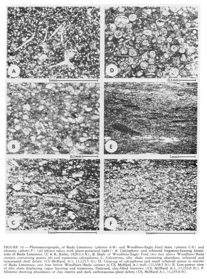 FIGURE 16. [Grey Scale] Photomicrographs, of Buda Limestone (photos A-B) and Woodbine-Eagle Ford shale (photos C-E) and siltstone (photo F) (all photos taken with plane-polarized light): A. Calcisphere- and echinoid fragment-bearing biomicrite of Buda Limestone (C & K, Kirby, 10,912.3 ft); B. Shale of Woodbine-Eagle Ford two feet above Woodbine/Buda contact, containing quartz silt and numerous calcispheres; C. Calcareous, silty shale containing abundant, echinoid and inoceramid shell debris (CS McHard, A-1, 11,225.5 ft); D. Close-up of calcispheres and small echinoid spines in micrite of Buda Limestone, one foot below Woodbine/Buda contact in CS, McHard A-1 well (11,358.5 ft); E. Low-power view of silty shale displaying vague layering and numerous, flattened, clay-filled burrows (CS, McHard A-1, 11,233.0 ft); F. Siltstone showing abundance of clay matrix and dark carbonaceous plant debris (CS, McHard A-1, 11,235.0 ft).
End_Page 510------------------------
in the shale; however, thin sections show abundant evidence of burrowing (Fig. 16E). Numerous compressed clay-filled burrow structures are evident, and quartz silt occurs not as distinct laminae, but as thin vague and irregular bands. The muddy sediment was probably originally highly bioturbated, but has developed a crude fissility owing to post-depositional compaction, dewatering and reorientation of clay particles. In part, the shale may display minor- to intense-soft-sediment deformation structures (Fig. 15; interval C) and slickensides (Fig. 15; intervals D, E, F), indicating slumping of semiconsolidated mud. Finely disseminated organic debris is relatively abundant in the dark gray shale; fifteen samples analyzed from the Cities Service, Sutton B-1 core (Fig. 11) revealed total organic carbon content ranging from 0.51% to 1.48% and averaging 0.80%. The organic material is a mixture of abundant structural (land plant derived) and common amorphous (marine algae derived) kerogen which has a thermal maturation index (TAI) of 2 to 2+ (Bill Meyers, Cities Service Research, personal communication, 1977). These shales are thought to be the source of the gas and condensate hydrocarbons being produced from the fractured sandstone reservoirs.
The major lithologic variations within the shale units include the presence of numerous thin sandy siltstone beds, abundant small discoid siderite nodules, and locally abundant calcareous shell debris. The light- to medium-gray (N7-N5) siltstone beds are locally numerous throughout the Woodbine-Eagle Ford interval (Fig. 11-12). Beds are generally 2 to 4 inches thick and may range up to 8 inches but rarely are as thick as 1 foot. They are composed of poorly- to moderately-sorted, medium- to very coarse-grained quartz silt, with common very fine-grained sand and abundant clay matrix (Fig. 15, interval G), and characteristically are very dense, being well cemented by clay and silica overgrowth. The beds display a variety of sedimentary structures, including small flute casts common on the bottom of beds (Fig. 15; intervals G, H, L), fine subhorizontal lamination, ripple-bedding, and abundant burrow structures. The lower bed contacts with shale are sharp and the upper surfaces are sharp to slightly transitional, but both may be modified by burrowing. Beds most commonly display lamination in the lower one-half to three-fourths and ripple lamination at the top (Fig. 15, intervals G, H, L), but they may be entirely laminated or almost entirely ripple-bedded (Fig. 17; interval A), or highly modified by burrowing (Fig. 15; intervals K, L).
Siderite nodules commonly occur throughout the shale lithofacies as small (from less than 1/2 inch up to about 1 inch thick and 1/2 inch to more than 2 inches across), dense, dark yellowish brown (10 YR 4/2) to brownish gray (5 YR 4/1) discoid-shaped nodules (Fig. 15; intervals I-J). The resistant nodules appear to contain abundant terrigenous clay and quartz silt, and display an internal massive bioturbate structure. The siderite nodules probably formed early as a replacement phenomenon and have preserved the bioturbate fabric of the mud, whereas the adjacent mud compacted around and over the nodules and displays a crude fissility.
Calcareous shell debris is abundant in the shale in the upper part of the Woodbine-Eagle Ford interval (Fig. 17. intervals B-C), and such an increase in abundance was noted in several cores, including: Cities Service, McHard A-1 and Sutton B-1 (Fig. 11 and 12), Cities Service, Exxon Fee A-1, and C & K, Kirby No. 1. The shell debris is mainly foraminifera and fragmented echinoid material, but disarticulated and fragmented bivalve material is also common, including prismatic inoceramid fragments (Fig. 16C). The shell debris increases in abundance upward into the Rapides Shale, which is interbedded with the Austin Chalk, and into the fossiliferous limestone of the lower part of the Austin Chalk.
Highly contorted, soft-sediment-deformed, intervals of clayey siltstone, silty shale and some very fine-grained silty sandstone are common in most cores observed through the Woodbine-Eagle Ford. The dominant textural and compositional difference between these deformed units and other lithofacies appears to be the abundance of clayey siltstone, although silty shale and thin sandstone beds may be present. The units display a swirled, (marble-cakelike) fabric of dark-gray shale, medium-gray siltstone and light-gray silty sandstone, with remnant layering commonly being vertical to overturned (Fig. 17; interval G). Abundant micro-faulting is present in more competent siltstone (Fig. 17; interval H), and slickensides are common in the shale. Thin (l/4-1/2 inch) silt layers in the shale commonly show micropull-apart thickening and thinning flowage structures, common in soft-sediment-deformed mud rocks (Fig. 17; interval I). Such structures suggest a fluid but semi-consolidated state for the deformed sediment.
The position of the contorted siltstone intervals within the vertical sequence is significant when attempting to interpret the origin of such deformation. In the Cities Service, Sutton B-1 core (Fig. 11) the three contorted intervals appear to be directly below the three main sandstone units, thus suggesting that the deformation could have been caused by the emplacement of the sand, or perhaps later by loading. However, closer examination indicates that the deformation may have occurred prior to sand emplacement. Shales and thin siltstone beds immediately below the sand bodies appear undeformed, and the sandstone units themselves are not deformed. Also note that in the Cities Service, McHard A-1 core (Fig. 12; depths 11,289-11,297 ft), a thick deformed unit occurs within an interval well below any major sandstone unit. Thus it appears that deformation due to slumping could have occurred without the influence of abundant and rapid sand emplacement.
Rapides Shale and Its Lower Contact
The Rapides Shale/Woodbine-Eagle Ford contact is one that is recognized on subsurface wire-line logs throughout Tyler and adjacent counties. The shale is characterized by a very low resistivity reading on the induction log below the Austin Chalk, and is the lowest log feature below the Austin Chalk that can be correlated persistently (Fig. 13 and 14). Because of its apparent lateral persistence, its rather uniform distance below the base of the Austin Chalk, and a highly variable distance to the top of the "first Woodbine Sandstone" below, the Rapides Shale/Woodbine-Eagle Ford contact has been considered by many to represent a regional erosional unconformity surface. However, where observed in core (Fig. 11, 12, and 18) there is no evidence for such unconformity.
Because the Rapides Shale directly overlies shale of the
End_Page 511------------------------
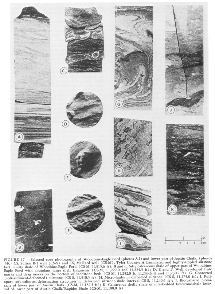 FIGURE 17. [Grey Scale] Selected core photographs of Woodbine-Eagle Ford (photos A-I) and lower part of Austin Chalk, (photos J-K) CS, Sutton B-1 well (CS-S) and CS, McHard well (CS-M), Tyler County: A Laminated and highly-rippled siltstone bed in silty shale of Woodbine-Eagle Ford (CS-M 11,315.6 ft); B and C. Silty calcareous shale of upper part of Woodbine-Eagle Ford with abundant large shell fragments (CS-M, 11,222.0 and 11,224.5 ft); D, E and P. Well developed flute marks and drag marks on the bottom of sandstone beds (CS-M, 11,232.8 ft, 11,233.6 ft and 11,230.2 ft); G. Contorted (soft-sediment-deformed) siltstone (CS-S, 11,318.5 ft); H. Micro-faults in deformed siltstone (CS-S, 11,273.0 ft); I. Pullapart soft-sediment-deformation structures in deformed siltstone-shale interval CS-S, 11,240.6 ft); J. Bioturbated biomicrite of lower part of Austin Chalk (CS-M, 11,187.5 ft); K. Calcareous shelly shale of interbedded limestone-shale interval of lower part of Austin Chalk/Rapides Shale (CS-M, 11,188.8 ft).
End_Page 512------------------------
upper Woodbine-Eagle Ford, it is difficult to pick the shale-on-shale contact in cores. The contact is identified only after careful correlation of the core with the wire-line log. After such correlation, the contact is recognized as one at which the Rapides is very slightly darker, softer, and less silty and calcareous than the shale below (Fig. 18). The Rapides Shale shows good fissility, having a poker-chip breakage character in core, and displays a few very thin, rippled silt laminae. The softness and erodability of the shale is revealed by its highly washed out character in core and in the well bore (see Caliper logs in Fig. 13 and 14). The shale contains common globigerinid planktonic and relatively deep-water benthonic foraminifera (Fig. 19A) similar to the Woodbine-Eagle Ford shale below. Thus, on the basis of lithologic and paleontologic data, it can be established that the Rapides Shale/Woodbine-Eagle Ford contact is not an erosional unconformity, especially not one created by subaerial exposure and erosion. The surface might however, represent a minor surface of non-deposition.
Austin Chalk (Lower Part) and Lower Contact
The upper 15 feet of the core from the Cities Service, McHard A-1 well contains interbedded clayey limestone and calcareous shale of the lower part of the Austin Chalk and upper part of the Rapides Shale (Fig. 12). The base of the lowest limestone bed in the core occurs at a depth of about 11,202+ ft; however, on the wire-line logs, the base of the Austin Chalk would he picked at about 11,192 ft (Fig. 14), at the base of a thick relatively uniform limestone interval. The lower contact obviously is a transitional and interbedded one with the underlying shale.
Limestone of the lower part of the Austin Chalk is a highly bioturbated (Fig. 17; interval J), mottled, light- to medium-gray, calcisphere-, echinoid-, and foraminiferal-bearing biomicrite (or wackestone) (Fig. 19B). Microspar (recrystallized micrite) and sparry calcite comprise 50 to 65% of the rock; fossil debris consists mainly of 30-50 micron-size calcispheres (15-25%), fragmented echinoid plates and spines (5-15%) and foraminifera (5-10%). Relatively large disarticulated and fragmented inoceramid clasts and other small bivalves are conspicuous in slabbed core and in thin section, but comprise less than 5% of the total rock volume. Quartz silt is present in minor amounts up to about 2 or 3%. Glauconite is present in a few scattered foraminifer tests and calcispheres, and small cubes of pyrite, up to 3% of the rock, are disseminated throughout the limestone.
Interbedded dark-gray to grayish-black fissile shale contains abundant calcareous fossil debris (Fig. 17; interval K; 19C). Such calcareous shale appears to contain abundant clay. However, precise measurements of the insoluable residue have not been made. Contacts with the interbedded biomicrite are gradational and have been modified by bioturbation.
SEDIMENTOLOGY OF SANDSTONE BODIES
General Lithology and X-ray Radiography
The excellent continuous Woodbine-Eagle Ford cores of the Cities Service, Sutton B-1 and the McHard A-1 wells, have provided sufficient material with which to properly analyze the depositional characteristics of the reservoir sandstone bodies in the Sugar Creek field area. Wire-line
 FIGURE 18. [Grey Scale] Core photographs of intervals containing the Rapides Shale/Woodbine-Eagle Ford contact in the CS, Sutton B-1 and McHard A-1 wells. The exact position of the, contact occurs within these 1.5 ft intervals, but can not be picked precisely, indicating the non-distinct character of the contact which some workers have mapped as a subaerial-erosional and angular unconformity.
End_Page 513------------------------
 FIGURE 19. [Grey Scale] Photomicrographs of Rapides Shale (photo A), Austin Chalk (photos B-C), and sandstone of Woodbine-Eagle Ford (photos D-F) (all photos taken with plane-polarized light, except as indicated): A. Rapides Shale containing abundant foraminifera (CS McHard A-1, 11,216.2 ft); B. Calcisphere- and echinoid-bearing biomicrite of Austin Chalk (CS McHard A-1, 11,187.8 ft); C. Calcareous clay-shale within lower part of Austin Chalk containing abundant quartz silt, carbonaceous plant debris, and echinoid and inoceramid shell fragments (CS Mchard A-1, 11,190.5 ft); D. Close-up of quartz arenite containing leached feldspar grain (F) (CS Sutton B-1, 11,301.2 ft); E and F. Plane-polarized light and cross-polarized light views of well-cemented quartz arenite containing a few calcareous rock-fragment grains (C) and displaying abundant quartz overgrowths throughout (CS Sutton B-1, 11,265.7 ft).
End_Page 514------------------------
logs of those wells indicate three distinct sandstone units in each (Figs. 13 and 14). The sandstones are separated by shale and/or siltstone units, and, except for thickness and minor complexity, they appear to he relatively similar to each other on the basis of log shape. It is important to note, however, that no apparent correlation exists between the sandstone units in the two wells (see Figure 10). Examination of the cores has demonstrated that the sandstone bodies are vastly more complex internally than would be expected from the well logs and that sandstone bodies may differ significantly from each other, even within a short distance in the same well (Fig. 11 and 12).
Observation of slabbed and polished cores of the sandstone reveals a rather uniform light- to very light-gray. dense and resistant, massive-appearing, fine- to very fine-grained, well-sorted sandstone with moderately common near-vertical fractures. "Massive" is used here to mean "without structure" and does not imply bed thickness; the term "massive-appearing" implies that a more ordered sedimentary fabric may be present but that it is not discernible under the observational conditions. The lower Sutton B-1 sandstone unit and the three McHard A-1 sandstone units contain numerous thin (1 inch) horizontal shale beds and may show minor clay laminae and a few small clay-lined burrows in some beds, especially the upper-most part of a few sandstone beds. The upper two Sutton B-1 sandstone units are essentially massive-appearing from bottom to top. The major sandstone units, and individual beds separated by thin shales, are characterized by very sharp lower and upper contacts and many display flute casts and other drag marks on the bottom of beds. (Fig. 17; intervals D, E, F).
Relatively little can be said about the depositional processes of massive sandstone beds with sharp upper and lower contacts, and since some units showed hints of lamination, it was thought that the beds may not be massive throughout. A few sandstone core pieces were cut into uniformly thick (3/8; inch) slabs, polished on both sides, and X-rayed with a commercial X-ray unit. The X-ray radiography revealed a great variety of internal sedimentary structures, so the entire sandstone core of both the Sutton B-1 and the McHard A-1 wells were X-ray radiographed. Although a great deal of the sandstone still appeared massive, numerous other sedimentary structures were revealed, including: subhorizontal lamination, cross-stratification, ripple-bedding, scour surfaces, soft-sediment-deformation structures, possible dish structures, and numerous burrow structures. Sandstone beds were analyzed in terms of the type and sequence of structures in order to determine the variety of genetic units present. Since sandstone composition, texture and rock fabric are significant characteristics of the genetic units, a brief discussion of sandstone petrography is provided below prior to a summary of sandstone genetic units.
Petrography
Sandstones of the Woodbine-Eagle Ford interval display a rather simple mineralogy and uniform texture and fabric. Overall, the sandstones are made up of about 55-70% framework grains, 5-15% visible void space, and 15-30% cement plus minor matrix. On the basis of framework composition, the sandstones are mainly quartz arenites, with some being sublitharenites, owing to the presence of calcareous rock fragments and minor amounts of chert. Framework grains are dominantly monocrystalline quartz (90-95% of framework fraction; Fig. 19E, F), with minor amounts of polycrystalline quartz (2-5%), feldspar (0-2%) and chert (0-2%). Small fossil fragments and reworked micritic carbonate clasts are common but are rarely more than 5% of the framework (Fig. 19E, F). Small shale and claystone clasts and fine carbonaceous debris are present in some samples. A few pelletoid grains of glauconite are almost always present, and heavy minerals (mostly zircon and tourmaline) are present in trace amounts. Observed feldspar is mainly of the potash variety; however, highly leached grains and void space, that probably were originally plagioclase (Fig. 19D) indicate that such grains may have been present up to 3 or 4% of the framework fraction. The secondary leaching of those grains has added significant porosity.
Visible porosity in thin section generally is less than 5%, but may range up to nearly 15%. Samples were impregnated with low-viscosity dyed epoxy so that actual rock porosity can be observed in thin section. Some porosity has resulted from the leaching of plagioclase grains. Porosity measured by conventional techniques in a commercial laboratory ranged from slightly less than 5% to 23% and averaged 12.8% (65 analyses). Measured permeability in horizontally oriented plugs ranged from less than 0.01 md to slightly more than 6.0 md in unfractured samples; 65 samples averaged 1.2 md with about one-fourth having values of 0.1 to less than 0.01 md, nearly one-half having values of 0.1 to 1.0 md and one-fourth with values of 1.0 to 6.0 md. Samples with natural fractures of course gave much higher permeability values and indicate the great importance of fractures in the overall reservoir potential of the Woodbine-Eagle Ford sandstones.
Diagenetic cement is abundant and may comprise up to 30% by volume of the sandstone. Generally at least two-thirds of the cement is silica in the form of quartz overgrowths (Fig. 19E, F), with calcite cement, chlorite grain coatings and void-filling kaolinite comprising the remaining cement. The virtual absence of detrital clay and silt matrix, and abundance of quartz overgrowths, and carbonate and clay cement has resulted in well-indurated resistent sandstone. Matrix-rich clayey siltstones and silty shales are considerably less well lithified.
Texturally the sandstones display several significant features. Grain size was measured in 78 sandstone thin sections from the Cities Service, Sutton B-1 core. Mean grain size ranged from 3.79 to 2.36 phi (72-195 microns; very fine- to fine-grained), and averaged 3.07 phi (120 microns ; very fine-grained). Sorting values ranged from 0.40 to 0.78 phi-units (well- to moderately-sorted) and averaged 0.56 phi-units (moderately well-sorted). Grainsize measurements were made by measuring the longest dimension of 100 grains per thin section. Quartz overgrowths could be delineated on most grains, and were accounted for so that original depositional texture could be estimated. No correction was applied to the thin section grain-size values. The general distribution of mean grain size and sorting value is indicated in Figure 20. Note the increase in sorting with decrease in mean grain size. The sandstones are amazingly free of detrital clay matrix, and the overall grain-size distribution within a sample (see Figures 21 and 22 showing typical grain-size histogram
End_Page 515------------------------
FIGURE 20. Relationship of mean grain-size and sorting for 78 thin-section samples measured from the sandstones of the CS Sutton B-1 core. Mean grain-size averaged 3.07 phi (120 microns) and sorting (standard deviation) 0.56 phi-units. The sedimentological significance of the inverse relationship for the matrixfree sand is discussed in the text.
FIGURE 21. Typical histogram of grain-size distribution for sandstones in Woodbine-Eagle Ford interval.
FIGURE 22. Typical log-probability grain-size distribution plot for sandstones in the Woodbine-Eagle Ford interval.
End_Page 516------------------------
 FIGURE 23. [Grey Scale] Photomicrographs of sandstones and conglomerate of the Woodbine-Eagle Ford (all photos plane-polarized light, except as indicated): A-B. Plane-light and cross-polarize-light view of quartz arenite displaying a subtle grainsize boundary; the uniform grain composition (shown in A) does not enhance stratification, but it can be seen in photo B with slight coarser quartz in lower half (CS-Sutton B-1, 11,290.5 ft); C-D. Plane-light and cross-polarized light view of quartz arenite displaying subtle stratification defined by slight variation in quartz grain size; such subtle lamination is very common in sandstones of the Woodbine-Eagle Ford in the study area (CS-Sutton B-1, 11,268.0 ft); E. Poorly-sorted, matrix-rich, quartz- and calcareous rock-fragment-bearing conglomerate of the diamict conglomerate bed in the Delta-Carter No. 2 well (14,046.3 ft); F. coarse-grained quartzose sandstone of the lower 0.5 ft of the graded sandstone bed in the Delta-Carter No. 2 well (14,040.1 ft); note abundant calcareous rock fragments and matrix.
End_Page 517------------------------
FIGURE 24. Genetic sedimentation units of the Woodbine-Eagle Ford sandstone bodies as observed, using X-ray radiography, in the CS Sutton B-1 core. The detailed character and significance of these units are discussed in the text.
End_Page 518------------------------
and log-probability plot) indicates that the sand has a relatively simple (one-population) grain-size distribution. Such textural features are related to depositional process, the signficance of which is presented in the discussion section. The vertical distribution of grain-size and sorting within a sandstone bed is described below in the discussion of genetic units.
The fabric of the sandstone units is interesting. Even though sedimentary structures such as lamination, cross-stratification, and burrows are present in the sandstone (revealed by X-ray radiography), they are extremely difficult, if not impossible, to discern in a polished core surface. Such is the result of almost no variation in grain size. Some stratification is delineated by a slight increase in clay matrix or by laminae containing fine clay clasts but most is defined by the minor variations in grain size, or merely by grain orientation (Fig. 23A, B, C, and D). Where the slightly elongate quartz grains orient with their long axes subparallel to layering, stratification is detected by X-ray radiography. Apparently the optic axis orientation of the quartz grains, which is usually related to the axis of elongation, has an effect on the propogation of X-rays through the sandstone and helps define the stratification present.
Sandstone Genetic Units
In order to infer depositional processes for lithologic units, such as the Woodbine-Eagle Ford sandstones, it is necessary to delineate genetic sedimentation units which represent the important depositional events. Genetic units can be delineated in cores on the basis of the type, relative abundance, and vertical distribution of sedimentary structures and rock fabric, combined with the character and vertical variation in composition and grain texture. It is also of critical importance to carefully observe and attempt to understand the upper and lower surface of the genetic units, since those surfaces represent significant processes such as nondeposition, erosion, pre- or post-deposition, biogenic reworking of sediment, and diagenetic events. The contact relationship between genetic units also indicate how the depositional process which formed each genetic unit began, and how it ended.
Sandstone Units of CS Sutton B-1 Well
Sandstone units of the Cities Service, Sutton B-1 core were studied in greatest detail, and provided the necessary data with which to delineate the major types of genetic units. Even in a very general way, it is possible to differentiate the three sandstone units of the core. As illustrated in Figure 11, the three sandstone units display the following general characteristics: 1) Lower sandstone unit is composed of numerous well-defined beds which commonly are burrowed at the top and are separated by thin shale beds. Beds vary from one another in texture and sedimentary structures; although the average mean grain size of the sandstone unit is 2.80 phi (145 microns, fine-grained, n-36), individual beds range from as coarse at 2.57 phi (170 microns, fine-grained), to as fine as 3.28 phi (103 microns, very fine-grained) but individually or collectively show no overall vertical grain-size pattern. 2) Middle sandstone unit is much finer grained than the lower or upper units, with an average mean grain size of 3.37 phi (96 microns, very fine-grained, n-19), and contains a variety of sedimentary structures, including well-defined cross-lamination, but does not contain thin shale beds or any burrow structures. The unit shows considerable grain-size variation internally, but does not display an overall fining- or coarsening-upward trend. 3) Upper sandstone unit is relatively coarse grained with an average mean grain size of 2.82 phi (140 microns, fine-grained, n-12) and displays a very uniform grain size throughout with no significant vertical textural trends. Also, thin shale beds and burrows are not present. These three sandstone units are amazingly dissimilar; it is somewhat surprising to find them vertically adjacent to each other in the depositional sequence.
The lower sandstone unit of the Cities Service, Sutton B-1 core is 22.7 ft thick and consists of at least 11 distinct beds with sharp lower and upper contacts and separated by thin shale beds. Most of the beds appear to represent genetic units although some are more complex than others and may be amalgamated units. The genetic units fall into three major categories (Fig. 24). Three of the eleven sandstone beds can be characterized as massive sandstone with burrows in the upper foot of the bed; the matrix-free sand is relatively coarse (2.4-2.8 phi; 190-145 microns; fine-grained) and moderately well-sorted (0.5-0.7 phi units) but not display textural grading; beds from 2 to over 7 ft thick fall into this category. One of these beds (depth interval 11,302.4-11,305.0 ft) is shown in Figure 25.
Most of the beds (7 of 11) can be characterized as laminated to massive, sandstone beds which commonly are burrowed in the upper foot. Grain size is variable from beds with an average grain size finer than 3.3 phi ( 104 microns; very fine-grained) to beds with a grain size as coarse as 2.6 phi (167 microns, fine-grained); textural grading is not well defined, with some beds displaying slight upward fining and others showing slight upward coarsening, suggesting that organized grading actually does not occur. Beds in this category range from about 1 to 2 ft thick. An example of two of these beds (depth intervals 11,297.2-11,299.7) is shown in Figure 26.
One bed in the lower sandstone unit is characterized by well-developed, trough-like cross-bedding (Fig. 27). The 2.3 ft thick bed (11,299.6-11,302.4 ft) contains massive sandstone near its base and laminated sandstones at the top, but is mainly composed of at least three cross-bed sets. The cross beds dip up to nearly 25 degrees, and are highly curved and tangential at the lower boundary of cross-bed sets, suggesting trough type cross-beds. The sand is relatively coarse with a grain-size of about 2.5 phi (175 microns, fine-grained) throughout, except for the top few inches which fine to about 2.75 phi (150 microns, fine-grained), giving a slight graded character to the bed. Burrows are not present in the bed.
The nature of burrowing in the lower sandstone unit is of significance. Burrows generally are narrow (0.1 to 0.2 inch) irregular cylindrical structures which disrupt bedding but may not be distinct structures themselves. Most burrows in the sandstones can only be detected by X-ray radiography; however, some structures are distinct clay-lined or clay-filled features. A few burrows up to 0.5 inch in diameter show well developed wall structures. Burrow orientation is variable from horizontal to inclined to vertical. Most burrowing is confined to the upper parts of sandstone beds, with some structures extending
End_Page 519------------------------
 FIGURE 25. [Grey Scale] Thick, massive (without structure) sandstone bed of lower sandstone unit, CS Sutton B-1 well. Note sharp contacts with thin shale beds and burrows in upper part of bed. Vertical change in mean grain size (M) and sorting (SD) is minor.
 FIGURE 26. [Grey Scale] Massive-to-laminated and laminated sandstone beds of lower sandstone unit, CS Sutton B-1 well. Note that the beds reveal relatively minor vertical grain-size changes, but differ significantly from each other in average mean grain size (M).
End_Page 520------------------------
 FIGURE 27. [Grey Scale] Cross-stratified sandstone bed of lower sandstone unit, CS Sutton B-1 well. The entire bed was slabbed in the same vertical plane; dip amount is apparent, but absolute changes in dip direction are real.
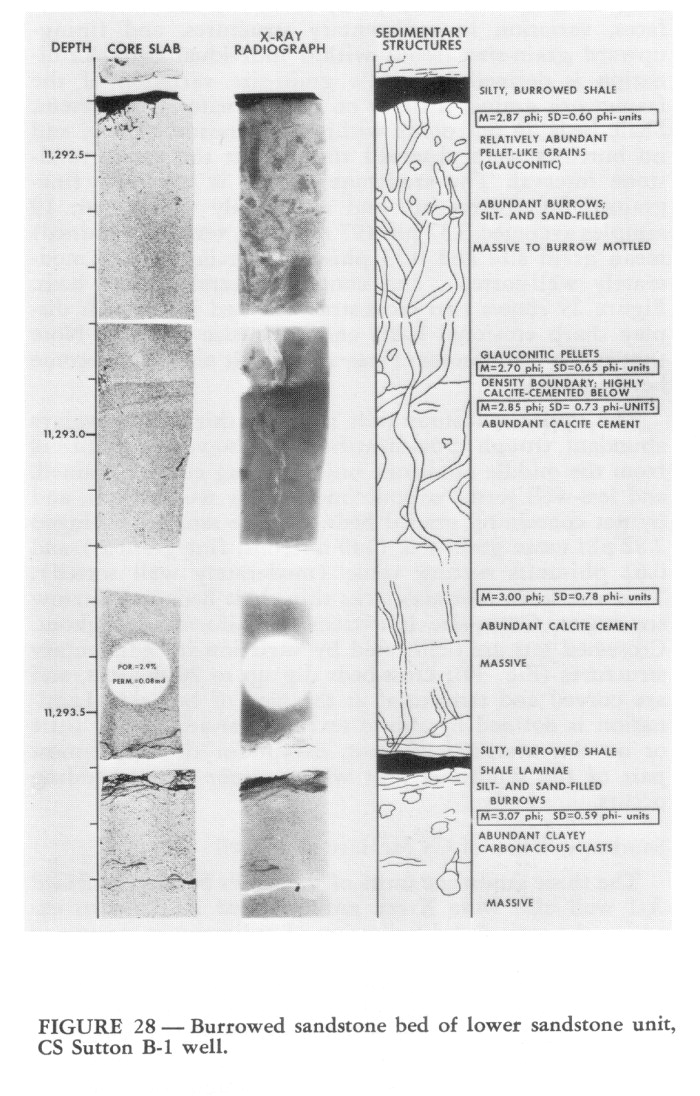 FIGURE 28. [Grey Scale] Burrowed sandstone bed of lower sandstone unit, CS Sutton B-1 well.
End_Page 521------------------------
over a foot downward. Complete bioturbation is present in some beds (Fig. 28), but most beds show only a few isolated structures. It is quite likely that beds which did not display burrows in the core may contain burrows just outside the core area. The structures probably represent burrowing by small decapod crustaceans and annelids.
The middle sandstone unit of the Sutton B-1 core is 6.5 ft thick, and consists of beds of massive-to-laminated sandstone and trough cross-stratified bed sets (Fig. 29). Bedding units are well-defined by scour-like truncation surfaces, variation in sedimentary structures, and fining-upward grain-size trends within individual beds. Lamination is defined by subtle grain-size variation of the framework grains; little or no matrix material is present. Shale beds do not occur within the sandstone body, and no burrows were observed throughout the entire sandstone interval. The sandstone overall is relatively fine-grained but matrix-free and moderately well-sorted; 19 samples averaged 3.37 phi (97 microns; very fine-grained) mean grain size and 0.53 phi-units sorting value (moderately well-sorted), and contains several graded beds. Figure 29 shows two cross-stratified bed sets which display sharp erosional bases and grain-size grading. Note that as the bed becomes finer upward, it also may become better sorted.
The upper sandstone unit is 7.4 ft thick and displays abundant trough cross-stratification; however, it differs from the middle sandstone unit in being coarser grained, and less-well sorted overall (moderately well-sorted), and by not containing graded beds. Twelve samples averaged 2.82 phi mean grain size (140 microns; fine-grained) and 0.62 phi-units sorting value (moderately well sorted). This sandstone unit also lacks thin shale beds and burrow structures. Grain-size is extremely uniform throughout. Cross-bed sets are delineated by variation in sedimentary structures (Fig. 30); cross-beds dip up to 20 degrees, and are curved and tangential at the base of bed sets. Lamination is defined by subtle textural variations and little or no clay matrix is present, except for the upper-most part of the sandstone unit where minor ripple-bedding occurs.
Sandstone Units of CS McHard A-1 Well
The three sandstone units of the Cities Service, McHard A-1 well also were X-ray radiographed in order to examine the type and distribution of sedimentary structures present. The major structures are summarized in Figure 12. In general, the major sandstone units are similar only to the lower sandstone unit of the Cities Service Sutton B-1 core. Sandstone beds are massive to laminated, separated by thin shale beds and commonly contain burrows confined mainly to the upper parts, although they may extend deeper into the beds than in the Sutton B-1 sandstone beds. No cross-stratification of the type observed in the middle and upper sandstone units of the Sutton B-1 core was observed in any of the McHard A-1 sandstones. Detailed grain-size measurements were not made, but McHard A-1 sandstone beds also are fine- to very-fine grained, well- to moderately-sorted, matrix-free and do not display obvious vertical textural patterns such as upward fining.
On the basis of such comparison, it appears that the most common genetic unit types are those that have sharp bases and tops, are massive, or are laminated and massive, are moderately well-sorted and uniform in grain size with no significant grading, and commonly display burrows in their upper parts.
DIAMICT CONGLOMERATE AND GRADED SANDSTONE UNITS OF DELTA, CARTER NO. 2 WELL
Part of the cored interval of the lower part of the Woodbine-Eagle Ford in the Delta, Carter No. 2 well contains a lithologic unit unlike that observed in any other core. The unit is a 13.5 ft thick zone of highly-contorted silty shale and shaly siltstone containing abundant gravelsize clasts up to several inches in diameter. The nongenetic term "diamict" (or "diamictite") has been used to refer to such nonstratified and nonsorted matrix-supported conglomerate (see Flint and others, 1960; Harland and others, 1966, p. 229). This somewhat anomalous unit deserves particular attention and is illustrated by a series of core Photographs (Fig. 31) and sketch correlated with the wire-line log (Fig. 32).
The 680 ft thick Woodbine-Eagle Ford interval of the Delta, Carter No. 2 well is dominantly shale with thin sandstone beds in the lower 170 ft (Fig. 32A). A 148 ft interval of core (13,970-14,118 ft log depths) was examined; however, only a 27.5 ft thick interval, containing the diamict conglomerate bed, is illustrated herein (Fig. 31). The 70 ft interval from below the diamict conglomerate and a deformed siltstone bed to the Buda limestone (log depth 14,060-14,130 ft) is dark gray to black, slightly silty shale with a few thin (1 to 2 inch) laminated- to ripple-bedded and burrowed siltstone beds. The shale is particularly characterized by inclined bedding surfaces (with respect to the near-vertical core hole), common slickensides, minor fault planes and some contorted bedding. Such structure is indicative of slump and mild-deformation of semi-consolidated mud. A 4.5 ft contorted siltstone bed, which directly underlies the diamict conglomerate, is well displayed in the core (Fig. 31), and expressed as a thin shaly sand on the SP log (Fig. 32A, depth 14,055-60 ft).
The conglomerate unit at a depth interval of 14,041.5-14,055 ft is expressed as shale on the SP log, but in core is observed to contain rounded to subangular pebble- to cobble-size clasts in a highly-contorted shaly mudstone matrix (Fig. 31). Clasts are composed mainly of micritic limestone, siltstone and laminated shale, fine-grained clayey sandstone (some calcite-cemented), sideritic mudstone, and disarticulated shell fragments. Very coarse sand-size and granule-size quartz grains are common throughout (Fig. 23E). Most rock fragments are pebble size and some clasts are up to 3.5 inches in diameter. Shaly clasts tend to be subangular, whereas limestone, sandstone and sideritic mudstone clasts commonly are well-rounded. Clasts range from light to dark gray with some yellowish-brown
End_Page 522------------------------
 FIGURE 29. [Grey Scale] Trough cross-stratified sandstone of middle sandstone unit, CS Sutton B-1 well. The entire unit was slabbed in the same orientation so that cross-strata throughout are revealed in the same vertical plane; dip amounts are apparent, but absolute changes in dip direction are real. Note scour surface at about 11,266.1 ft and minor soft-sediment deformation structures at 11,264.9-265.4 ft. Also note the graded (fining-upward) character of the cross-bed sets.
End_Page 523------------------------
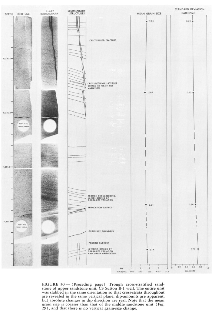 FIGURE 30. [Grey Scale] Trough cross-stratified sandstone of upper sandstone unit, CS Sutton B-1 well. The entire unit was stabbed in the same orientation so that cross-strata throughout are revealed in the same vertical plane; dip-amounts are apparent, but absolute changes in dip direction are real. Note that the mean grain size is coarser than that of the middle sandstone unit (Fig. 29), and that there is no vertical grain-size change.
End_Page 524------------------------
brown sideritic mudstone; matrix is light to medum gray. There appears to be a complete lack of sorting, with clasts being supported entirely by the silty shale matrix. Grading also appears to be absent, although the largest clasts are more abundant in the lower half of the unit. Deformation is intense with irregular folding, pull-apart structures, and micro-silt-filled clastic dikes, but no obvious microfaults. These structures and the presence of remnant lamination indicate that deformation occurred while the sediment was in a semiconsolidated state.
A 6.5 ft thick graded, massive- to laminated- to ripplebedded sandstone bed directly overlies the diamict conglomerate. Massive, medium- to coarse-grained sandstone in the lower part of the unit grades upward to laminated and ripple-bedded fine- to very fine-grained sandstone in the upper part (Fig. 31). The dense, very light-gray (N8) to yellowish-gray (5 Y 7/2) sandstone has a framework/cement/void space ratio of about 75/23/2, with the framework being mainly subangular to subrounded quartz (90-95%). Micritic limestone clasts, fossil fragments and reworked shale clasts comprise most of the remaining framework grains (Fig. 23F). Silica in the form of quartz overgrowths comprises about 40-50% of the cement; calcite ranges from about 24 to 35% of the cementing fractions, and authigenic clay (mainly chlorite) about 20 to 35%. The basal contact of the sandstone is irregular, and the largest shale clasts and calcareous rock fragments are concentrated in the lower one-half foot. Small dark shale clasts and minor carbonaceous debris is randomly distributed in the lower massive sandstone, but is concentrated on laminae surfaces in the upper laminated and rippled sandstone. The upper sandstone contact is sharp with the overlying shale.
A two-foot bed of dark-gray silty shale directly overlies the graded sandstone bed and is overlain by 2.5-3.0 ft of very fine-grained laminated sandstone with interbedded shale. The 50 ft interval from 13,980 to 14,030 ft is darkgray silty shale with numerous thin, laminated- to ripplebedded, very fine-grained sandstone and coarse siltstone beds. The prominent 10 ft sandstone on the well log at 13,920 to 13,980 ft is composed of massive to laminated fine- to very fine-grained sandstone, similar to that observed in the Cities Service, Sutton B-1 and McHard A-1 cores.
SUMMARY AND SIGNIFICANCE OF OBSERVATIONS
Table 2 summarizes the observations made in this study and lists basic inferences which have been made from each point of data. When attempting to combine such numerous and divers observations into an overall pretative depositional model, it is helpful to first consider the basic significance of each point. The best interpretation, of course, is the most simplistic one which explains all of the observations; the significance of each point of data must not be underemphasized.
Significance of Tectonic. Setting and Clastic Wedge
The tectonic setting is probably the most important factor affecting sedimentation, and an attempt always should be made to understand as much as possible about the regional and local tectonic characteristics of the source area(s) and receiving basin. Information about the regional tectonic setting has been derived from literature sources such as Granata (1963), Stehli et al. (1972), Hendricks and Wilson (1967), and Nichols (1964). Such information indicates that deposition of the Woodbine-Eagle Ford in Tyler County occurred slightly basinward of a very narrow continental shelf, just north of which was an active area of positive relief undergoing subaerial erosion. The Cretaceous shelf edge, as indicated by the Angelina-Caldwell flexure and Lower Cretaceous reef buildups. and the Sabine Uplift are well-defined features, and their influence on Cretaceous depositional patterns has been discussed in many papers on East Texas and Louisiana geology. Of particular significance in the northern Tyler County area is the short distance between the postulated southern edge of the exposed Sabine uplift and the continental shelf edge. In such a setting it is very likely that sediments could be easily transported across the narrow shelf and deposited down the slope. Farther to the west and southwest, where the shelf edge swings southwestward, the Woodbine-Eagle Ford marine shelf was much broader (see Oliver, 1971). In that area it would be more difficult to transport sand across the shelf and down the slopes.
The subsurface log correlation and seismic section (of Sheriff, 1976) emphasize the spectacular nature of the Woodbine-Eagle Ford clastic wedge. The lack of sand on the relatively flat shelf surface north of the Edwards reef trend suggests that sediment by-passed that area and moved directly down-dip where it was deposited,on the slope. The paleotectonic configuration of the basin floor is relatively well defined by the Buda Limestone surface. Inclined reflectors within the Woodbine-Eagle Ford interval probably represent surfaces of a prograding shelf margin and slope. Most sand in the Woodbine-Eagle Ford interval, where the inclined reflectors occur, is in the lowermost part of the formation. Therefore it is suggested that some sand moved across the slope surface and was deposited at the base of the slope. The inclined reflectors probably do not represent actual sand bodies, but are a record of the prograding muddy slope surface.
Significance of the Stratigraphic Sequence
When interpreting the depositional environment of a particular stratigraphic unit, it is extremely important to attempt an understanding of its genetic relationships with units vertically and laterally adjacent. The composition and texture of the Buda Limestone suggests that it was a deep water carbonate-ooze type deposit. The distinct but unquestionably transitional contact with the Woodbine-Eagle Ford shale indicates that Buda lime mud deposition ended with a relatively sudden influx of terrigenous mud into the deep-water environment. There is no evidence of submarine or subaerial erosion at the top of the Buda Limestone, where observed in core in this study.
The top of the up-dip Woodbine Formation in much of northeast Texas is well documented and widely recognized as an erosional unconformity. However, in the
End_Page 525------------------------
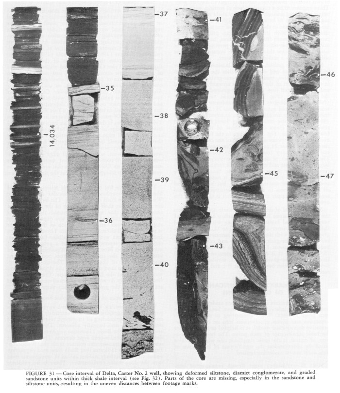 FIGURE 31. [Grey Scale] Core interval of Delta, Carter No. 2 well, showing deformed siltstone, diamict conglomerate, and graded sandstone units within thick shale interval (see Fig. 32). Parts of the core are missing, especially in the sandstone and siltstone units, resulting in the uneven distances between footage marks.
End_Page 526------------------------
 FIGURE 31. [Grey Scale] See caption on page 525.
End_Page 527------------------------
down-dip area of this study, no such erosional unconformity is evident. The base of the Rapides Shale (which is the lowest, most wide-spread correlation surface below the Austin Chalk) is very difficult to distinguish lithologically or paleontologically (same fauna above and below), and simply is not a surface of subaerial or submarine erosion. The surface may represent a significant, but not yet determined, period of nondeposition. Since the Rapides Shale grades into the Austin Chalk, the Rapides actually may be genetically more related to Austin Chalk deposition. Thus, the base of the Rapides may represent a subtle end of Woodbine-Eagle Ford deposition and beginning of Austin Chalk deposition. Perhaps a sudden sea level rise inundated the Sabine positive area and cut off the supply of terrigenous clastic sediments. The lower part of the Austin Chalk is lithologically similar to the Buda Limestone and also may represent relatively quietwater carbonate mud deposition.
Overall, the general character of the down-dip Woodbine-Eagle Ford clastic wedge is that it is dominantly mud. Even where sandstone bodies are relatively thick, in the area just south of the Edwards reef trend, they are discontinuous lenticular bodies encased in silty shale. The sharp contacts at the base and top of sandstone beds indicate that sand deposition began and ended quickly in an otherwise relatively quiet-water environment. The thin, graded, laminated to ripple-bedded siltstone beds within the shale units also indicate periodic influx of current-transported and-deposited sediment into an environment which most of the time was characterized by suspension sedimentation of mud. The probable types of currents depositing the sandstone and siltstone beds is discussed in the following sections on structures and textures.
Siderite nodules in the shale indicate relatively early post-depositional formation below the sediment/water interface. The environment was probably an oxidizing one above the sediment surface and within the upper few centimeters of bioturbated sediment. However below that, the conditions probably were reducing, permitting the formation of siderite. Siderite formation and replacement of clay minerals preserved the bioturbate fabric of the mud; later compaction caused the enclosing mud to develop a crude shale fabric which is warped under and over the more resistant nodules.
Several factors appear to have contributed to the formation of the contorted siltstone units. The abundance of clayey silt material probably was a major factor. Silt appears to have an affinity for penecontemporaneous deformation since it is porous enough to contain abundant interstitial water, like sand, but too impermeable to easily release the water during pressure changes. The relatively steep slope angle undoubtedly was another factor; a slope of less than one degree actually could contribute to such sediment deformation if other conditions were favorable. The rapid influx of sand also may have had a direct influence on the deformation of the soft silt deposits. Either the event which also triggered the sand influx, or the actual rapid loading of the sand in a water-saturated silty substrate could have caused the deformation. The potential for all of these factors probably was present in the depositional setting of the Woodbine-Eagle Ford in the Tyler County area.
Geometry of the major sandstone bodies also can be partly inferred from the general stratigraphic sequence. Sandstone bodies are relatively lenticular and isolated within the muddy clastic wedge. Correlations are extremely poor to nonexistent along strike. The best correlation is in a down-dip direction although subsurface control is too poor to be able to properly assess even that. It is very unlikely that the sandstone bodies are strike-oriented and thus quite probable that they are dip oriented.
Significance of Microfauna and Kerogen Content
The significance of the foraminiferal paleoecological data cannot be over-emphasized. Paleoecological data (micro- or macro-faunal) always should be obtained when possible, and considered in conjunction with the stratigraphic and sedimentologic observations. The abundance of open-marine planktonic and outer shelf-upper slope benthonic foraminifera in the silty shale simply indicates a relatively deep water (>600 ft) setting. The presence of near-shore arenaceous benthonic forms in the sandstones obviously indicate that they were transported from a nearshore environment to a deep-water environment with the sandstone.
The abundance of structural kerogen in the shales indicates a relatively short distance from the shore line. Abundant land-derived plant debris was transported into the marine environment and mixed with the amorphous kerogen derived principally from marine algae. The abundance and preservation of land-derived plant material may indicate a deltaic source and rapid deposition.
Significance of Sandstone Sedimentary Structures, Texture and Composition
Based on the detailed analysis of abundant data, the sandstone units are interpreted to have been deposited rapidly in a relatively deep marine setting by low- to high-concentration density currents and by tractive currents. The genetic sedimentation units are not those of classical turbidite beds (such as discussed by Middleton and Hampton, 1973; Walker, 1965; and many others), but nevertheless appear to be gravity-influenced resedimented sand. The sharp, fluted base and dominantly massive, and laminated-to-massive sand, suggest rapid influx and deposition of density-driven sediment flows. Such beds are comparable to the "grain-flow" beds of Stauffer (1967), however, the concept of grain-flow is not well understood or accepted and is not invoked as a specific process of deposition. for the Woodbine-Eagle Ford sandstone beds. Sharp non-graded bed tops with downward-penetrating burrows indicate a sudden cessation of sand deposition, without subsequent suspension deposition of a cloud of silt and clay (as in a classical turbidite), and then burrowing during a relatively long time of mud suspension deposition before another sand layer was deposited. Ripplebedding (again a common part of the classical turbidite bed) is only rarely observed in the sandstone beds; its absence is difficult to comprehend entirely.
The thin siltstone beds of the shale units are interpreted as typical "distal turbites" analogous to those discussed by Walker (1967). They have sharp, fluted bases and grade upward froth laminated to rippled coarse clayey silt. Since such siltstone bed-hearing sequences occur interbedded with the thicker sandstone units, they probably are not significantly distal to the sandstone deposits but may
End_Page 528------------------------
FIGURE 32. Wire-line SP-Induction log of Delta, Carter No. 2 well and sketch of core interval containing diamict conglomerate and graded sandstone units. The entire core interval examined is indicated by the solid black bar on the log; the core interval illustrated in Figure 31 and by the sketch is indicated by the cross-ruled bar.
FIGURE 33. Conceptual model for submarine-fan deposition of Woodbine-Eagle Ford, central-northern Tyler County, Texas.
End_Page 529------------------------
TABLE 2. Summary of important observations and their implications involved in the paleoenvironmental interpretation of the Woodbine-Eagle Ford interval of Tyler County, Texas
End_Page 530------------------------
more likely be a lateral facies. The presence of such thinbedded turbidites further supports the interpretation of the sandstone units as submarine density-current deposits.
The presence of well-developed trough cross-stratification is a particularly difficult observation to interpret. Such cross-bedding is neither common in submarine density-current deposits, nor is it common in such fine- to very fine-grained sandstone. However, based on its association within this sedimentary sequence, it is thought to have developed by the tractive transport of a sandy bed-load by relatively low-concentration density currents. The thickness of cross-bed sets suggests that one- to two-foot-high sand dunes were formed on the sandy substrate. In order to form such structures in fine sand, moderately strong tractive currents would have had to flow at a relatively continuous velocity for a relatively long time. Flow certainly would have been more continuous, and for a longer period of time than would be expected for a typical turbidite. The formation of such cross-bedding has been reported in ancient sandy and gravelly deposits also thought to represent deep-water resedimented deposits (e.g., Winn and Dott, 1977; Kessler et al., 1976).
The texture of the sandstone also suggests something about the depositional process. Simple, one-population, grain-size distributions are indicative of transport of the entire sediment by one mechanism, such as by saltation or by suspension. Turbidite beds commonly display such a grain-size distribution (Roderick Tillman, personal communications, 1977). The lack of matrix in the well- to moderately-sorted quartzose sand, which occurs in a mud-dominated depositional setting, suggest that mud was winnowed out of the sand either during transport or possibly before transport to its final resting place. Since the sandstone also displays an inverse relationship between grain size and sorting (i.e., the finer grained the sand the better its sorting), it is postulated that the sand was winnowed prior to transport. Normally where there is a wide grain-size range of material available, such as in the Woodbine-Eagle Ford interval, where finer-grained sandstones are typically less well-sorted. The inference here is that the sand was winnowed in a near-shore environment (possibly a beach), providing a well-sorted sand of limited grain size range. The sand was then transported and redeposited down-dip, and, as the sand was deposited, the relatively coarser part was deposited first and the relatively finer material slightly later. Since no new fine material (silt and clay) was added to the sand during transport and deposition, selective sorting resulted in better sorting in the relatively fine sand. The general lack of grading in the sandstone beds is, to a great extent, due to the relatively narrow grain-size range of sand available for redeposition in the deep-water setting.
The composition of terrigenous clastics commonly is not particularly suggestive of a particular depositional environment. Detrital components like those of the Woodbine-Eagle Ford sandstones are not unexpected for the type of deposit inferred on the basis of other more significant data. The dominance of quartz obviously indicates recycling of a sedimentary rock source and reworking in a high-energy environment. Calcareous lithic fragments indicate erosion of a limestone unit. Although the clasts have not been identified as indicative of any particular lithic unit, they may represent subaerial erosion of Lower Cretaceous carbonate units in the positive area of the Sabine uplift. It should be stated that none of the clasts contained calcispheres and thus could not he attributed to the Buda Limestone. Shale intraclasts indicate intrabasinal redeposition of at least semiconsolidated mud. Carbonaceous debris indicates a probable deltaic source, and glauconite is indicative of a marine depositional setting.
Significance of the Diamict Conglomerate
The diamict conglomerate unit and overlying graded sandstone bed in the downdip Delta, Carter No. 2 well most probably represent a submarine debris flow and turbidite, possibly as parts of the same event. The relatively well-rounded pebbles and cobbles represent erosion, transport and reworking in a continental to nearshore setting. Their transport downslope into a muddy deposit could have been as a gravity debris flow. Deposition into, and mixing and mass retransport with the soft mud, resulted in the contorted and nonorganized, mud-supported conglomerate. Deposition of the graded sand turbidite above could have occurred as the tail of the debris flow, or merely as a subsequent event.
Because of the distance of the Delta, Carter No. 2 well from the Sugar Creek Field area and the lack of sufficient subsurface control, it is difficult to determine the relationship between the sedimentary sequences of the two areas. The relative age of the two squences is not known. The fact that the coarsest sediment in the Woodbine-Eagle Ford occurs in the farthest down-dip position observed, suggests that it may have by-passed the up-dip area. Whatever triggered transport of the gravel debris flow was intense enough to cause the sediment to move far downdip into the basin.
DEPOSITIONAL MODEL
The depositional model for the Woodbine-Eagle Ford sequence of central northern Tyler County, has been conceptualized primarily from the information summarized in Table 2 and discussed above. The conceptual model is illustrated in Figure 33 and briefly explained below.
Basically the model is one in which sediment was transported around and across the exposed Sabine uplift, across a narrow marine shelf, and down the slope where it was deposited in a slope fan-lobe system. The character of the up-dip Woodbine has been well-documented by Oliver (1971) as a coastal-plain deltaic system with abundant near-shore marine (delta-destructional) deposits. The exposed and eroded Sabine uplift also probably provided sediments to the near-shore area. The coastal-plain and deltaic system may have prograded to near the edge of the continental shelf in the area south of the Sabine uplift. Abundant muddy sediment was contributed to the slope as it prograded seaward.
Reworked nearshore marine sand periodically was transported across the narrow shelf and channeled down-slope through breaks in the shelf "edge". The exact nature of such transport is difficult to conceptualize, but it is postulated that such sediment flow had to be channelized at some point at the shelf/slope break or farther landward. The most convenient process would have been for the nearshore sand to be transported by longshore currents directly into the mouth of a shelf or shelf-edge submarine
End_Page 531------------------------
canyon of some sort. There is no direct evidence of such canyons, but breaks would certainly be expected in a shelf edge such as the Lower Cretaceous one in East Texas where reef buildups are well known. Shelf-edge reefs are characteristically discontinuous along strike and have significant channel-ways between them.
Sands were deposited as narrow, dip-oriented channel-like bodies in a fan-lobe system. Lateral and distal to such channel deposits are the silty shales with thin-bedded turbidites. The fan lobes were very dynamic deposits with channels shifting with time back and forth across the fan, and major lobes interfingering laterally and distally with other lobes. Sand deposits probably terminate updip near the shelf/slope break since sand most likely was transported through, but not deposited in, the shelf and shelf-edge feeder channels. Subsequent mud deposition over such sand deposits later provided updip seals to hydrocarbon migration. The downdip extent of the postulated lobes in the Sugar Creek area has not yet been determined by drilling. The position and character of the diamict conglomerate unit of the Delta, Carter No. 2 well is not included in the conceptual model (Fig. 33), but is postulated to represent a debris flow which initiated near the shelf edge and to have by-passed the upper-slope fanlobe system.
Basin progradation of this slope system continued as long as sediment was supplied in abundance, resulting in construction of a broader shelf. Eventually sediment supply was terminated, possibly by a sea level rise, and deposition of the Rapides Shale and Austin Chalk occurred across the entire area.
Pay-Per-View Purchase Options
The article is available through a document delivery service. Explain these Purchase Options.
| Watermarked PDF Document: $16 | |
| Open PDF Document: $28 |