The AAPG/Datapages Combined Publications Database
AAPG Bulletin
Full Text
![]() Click to view page images in PDF format.
Click to view page images in PDF format.
AAPG Bulletin, V.
DOI: 10.1306/04042322097
Use of exploration methods to repurpose and extend the life of a super basin as a carbon storage hub for the energy transition
J. R. Underhill,1 I. de Jonge-Anderson,2 A. D. Hollinsworth,3 and L. C. Fyfe4
1Interdisciplinary Centre for Energy Transition, School of Geosciences, University of Aberdeen, King’s College, Aberdeen, Scotland, United Kingdom; [email protected]
2Institute of GeoEnergy Engineering, School of Energy, Geoscience, Infrastructure, and Society, Heriot-Watt University (HWU), Edinburgh, Scotland, United Kingdom; [email protected]
3Institute of GeoEnergy Engineering, School of Energy, Geoscience, Infrastructure, and Society, HWU, Edinburgh, Scotland, United Kingdom; [email protected]
4Institute of GeoEnergy Engineering, School of Energy, Geoscience, Infrastructure, and Society, HWU, Edinburgh, Scotland, United Kingdom; [email protected]
Abstract
The Anglo-Polish Super Basin forms an important petroleum province that stretches across northwestern Europe. It contains many giant gas fields, primarily located beneath a thick upper Permian (Zechstein Group) evaporite canopy and a smaller amount of oil and gas in Mesozoic reservoirs in the suprasalt section. Although exploration activity continues in the super basin, discoveries have diminished in size; many fields have been decommissioned; and it is beginning a transformation from an area with a rich petroleum heritage to a new, low-carbon energy hub. Given its favorable geology, infrastructure, and the location of major industrial emitters in adjacent land areas, offshore parts of the super basin are being evaluated and repurposed for renewable technologies like wind and geothermal energy, and as possible sites for subsurface carbon dioxide, hydrogen, compressed air, and methane gas storage.
The use of a rich, dense, and high-fidelity seismic, well log, core, and pressure data sets acquired during petroleum exploration and production activities provide the basis for a play-based exploration assessment of the super basin’s carbon storage potential. The results of our analysis of the super basin’s offshore waters of the United Kingdom sector suggest that storage in traps containing Carboniferous and Permian (presalt) and Triassic (postsalt) clastic reservoirs have the potential to extend the life of the mature super basin during the energy transition. The detailed evaluation of the Rotliegend Group, from which most of the gas in the basin has been derived, enables a prospective subsalt carbon storage reservoir play fairway to be defined, common risks to be identified, and composite maps to be produced that show where the best storage locations are situated. Similarly, mapping of depleted fields and dry closures created by salt mobility (halokinesis) that contain Triassic Bacton Group (Bunter Sandstone Formation) reservoirs provides the basis on which to build a carbon storage prospect and lead inventory in the suprasalt section. In addition to the geological criteria, our results highlight the need to be aware of nongeological risks including the integrity of the legacy well stock and colocation issues that arise from the competition for offshore areas, especially wind farms fixed to the sea bed, since these can constrain the areas available for carbon storage that lie below them.
INTRODUCTION AND AIMS
Petroleum super basins are defined as those basins that have produced more than 5 billion BOE and hold additional recoverable reserves of 5 billion BOE or more (Sternbach, 2018, 2020). More than 40 super basins have been recognized globally, 10 of which contribute over three-quarters of the world’s total oil and gas production. With an increasing awareness of the need to pivot toward sustainable energy resources to meet global emission targets, there is more of a focus on super basins containing “advantaged resources” that can be decarbonized such that their indigenous reserves have a lower carbon footprint compared to oil and gas imports that would otherwise be needed, or areas that have the potential to be transformed for a low-carbon renewable energy future. Although not an energy source, carbon capture, utilization, and storage (CCUS) holds the potential by which emissions generated by power plants and heavy industrial sources may be sequestered and safely stored rather than being released into the atmosphere. In so doing, the possibility exists to ensure energy security is maintained and net zero emission targets achieved.
The aim of this paper is to use play-based exploration (PBE) methods traditionally used in the subsurface interpretation of prospective petroleum basins to examine and test whether the Anglo-Polish Super Basin of northwestern continental Europe in general and the United Kingdom sector of the Southern North Sea in particular present a carbon storage opportunity. The results highlight the stratigraphic intervals and geographical areas that have the best potential for carbon storage as a means to meet net zero targets, transform the energy system, and extend the life of a petroleum super basin.
THE ANGLO-POLISH SUPER BASIN
Definition and Its Classification as a Petroleum Super Basin
The Anglo-Polish Super Basin stretches from eastern England to central Poland, a distance of >900 km and a width of >350 km to encompass onshore areas and shallow offshore waters in five countries (United Kingdom, the Netherlands, Germany, Denmark, and Poland; Figures 1, 2). The super basin was created by north-south–directed crustal stretching during the Permian. It is separated from a northern counterpart by the Mid North Sea high (Figure 1).
Due to the age of their formation, the basins are commonly referred to as the Southern Permian Basin and Northern Permian Basin, respectively (e.g., Glennie and Underhill, 1998; Doornenbal and Stevenson, 2010; Doornenbal et al., 2022). However, to avoid confusion with and make it distinctive from the Permian petroleum super basin of West Texas, the Anglo-Polish Super Basin descriptor is used in this paper. Although it is common to see the Anglo-Polish Super Basin subdivided into three component parts—the Anglo-Dutch, North German, and Central Polish subbasins—these areas largely reflect geopolitical and socioeconomic considerations rather than geological ones (Ziegler, 1990) and are not used here.
 Figure 1. Location and extent of the Anglo-Polish Super Basin and its northern counterpart, the Northern Permian Basin. Both basins and the Mid North Sea high that separates them formed in response to north-south Permian rifting.
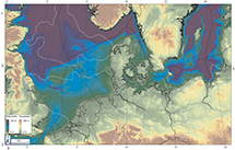 Figure 2. Topography (Copernicus, 2010) and bathymetry (EMODnet, 2020) of the Anglo-Polish Super Basin and the Northern Permian Basin. The white lines correspond to the outlines of the Anglo-Polish Super Basin and its Northern Permian Basin counterpart. In contrast to other parts of the North Sea Basin, offshore areas of the Anglo-Polish Super Basin lie in relatively shallow waters (less than 50-m depths), meaning that they are more conducive to renewable technologies such as fixed wind installations leading to a competition for offshore areas.
The Anglo-Polish Super Basin has proven to be an extremely prospective petroleum system that hosts more than 1350 oil and gas fields (Peryt et al., 2010). Several petroleum systems (sensu Magoon and Dow, 1994) exist, the most notable of which are charged by Carboniferous (Mississippian and Pennsylvanian) and Jurassic (Liassic and Malm) source rocks. Oil shows have also been recorded from upper Permian (intra-Zechstein) sources locally.
The super basin is dominated by gas (26.33 billion BOE; 95.5%) rather than oil, which only contributes 1.7 billion BOE (4.5%), reflecting the nature and maturity of the Carboniferous source rocks. Gas production is predominantly from the Rotliegend Group reservoirs (Figure 3), which account for 185 TCF (88%) of the total volumes, with the Triassic (14 TCF, 7%), Carboniferous (6.2 TCF, 3%), and Zechstein reservoirs (4.2 TCF, 2%) (Breunese et al., 2010). Overall production from the basin is now ∼210 TCF making it consistent with Sternbach’s (2018, 2020) classification as a petroleum super basin.
 Figure 3. Pie charts showing the reservoir host for gas production in the basin (A), the dominance of gas over oil production (B), and the relative distribution of gas reserves in the Anglo-Dutch part of the Anglo-Polish Super Basin (C). NL = the Netherlands; UK = United Kingdom.
The Groningen field accounts for well over half (100 TCF) of the reserves in Rotliegend Group reservoirs. Of the rest, another 105 TCF of gas is located in the United Kingdom and Dutch sectors of the Southern North Sea, with the United Kingdom Southern North Sea hosting 159 gas fields, three-quarters of which involve Permian reservoirs (Figure 4). The record of gas production from the United Kingdom sector shows that more than 35 TCF of the 55 TCF of United Kingdom reserves have been produced from the region over the four decades for which reliable records are available (North Sea Transition Authority, 2022), with gas production peaking in the mid-1990 s (Underhill and Richardson, 2022). Since that time, the United Kingdom has returned to being reliant on imports to meet its needs.
 Figure 4. Production curves for the United Kingdom and Netherlands sectors of the Anglo-Dutch offshore sector of the Southern North Sea highlighting the fields and volumes that justify the Anglo-Polish Super Basin’s designation as a petroleum super basin. The basis for the diagram comes from a variety of sources, including the North Sea Transition Authority, Netherlands Organisation for Applied Scientific Research, and Doornenbal et al. (2022). The diagram emphasizes the dominance of the Rotliegend Group as a productive reservoir and reserves in the Groningen field dwarf other discoveries. eq. = equivalent; PJ = petajoule; STOIIP/GIIP = stock tank oil initially in place/gas initially in place.
The extensive exploration and production activities have resulted in the acquisition of high-fidelity seismic data sets over most of the Anglo-Polish Super Basin, including near-blanket coverage of the offshore waters by three-dimensional (3-D) data (e.g., in the United Kingdom Southern North Sea; Figure 5) and an extensive network of pipeline infrastructure serving onshore refineries. The wealth of data derived from its petroleum heritage provides an excellent basis for understanding its stratigraphic development and evolution.
 Figure 5. Map of three-dimensional (3-D) seismic data sets, wells, fields, pipelines, and onshore terminals for the east coast of England and the Southern North Sea. Seismic data from the National Data Repository (NDR) and the United Kingdom Onshore Geophysical Library (UKOGL) emphasize the near-blanket data coverage that forms the foundation for characterizing the subsurface in the super basin. Spec = speculative seismic data coverage, not currently released to the public.
Tectonic History and Sedimentary Fill
The variability in the subsurface geology across the elongate, west-east–striking, canoe-shaped basin is well constrained by the thousands of boreholes that have penetrated strata, more than 2000 of which are located in the United Kingdom sector. Having been the site of so much exploration activity, not just from an oil and gas perspective but also resulting from coal mining activities, mineral exploration, and geothermal investigation, the detailed basinal structure, stratigraphy, and petroleum systems of the Anglo-Polish Super Basin are very well defined (Figure 6).
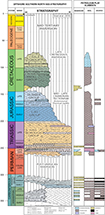 Figure 6. Stratigraphy and petroleum elements of the Southern Permian Basin, United Kingdom. The stratigraphic chart is from Grant et al. (2018). Fm. = Formation; GP. = Group; Mb. = Member; SGP = Supergroup.
Deeper well penetrations have demonstrated that the Anglo-Polish Super Basin lies on the eroded roots of the foreland to the Variscan mountain belt and its Caledonian precursor. The Caledonian plate cycle recorded the development, evolution, and closure of the southwest-northeast–striking Iapetus Ocean and a subsidiary northwest-southeast branch termed the Tornquist Sea (Glennie and Underhill, 1998; Underhill, 2003). The interaction between the two orogenic systems led to the development of a northerly pointing, triangular massif called the Anglo-Brabant massif. The Caledonian events imparted a strong underlying southwest-northeast– and northwest-southeast–striking structural fabric with a long-lived history of reactivation that governed subsequent deformation including the formation of numerous structural traps.
The Caledonian Orogeny was succeeded by the Variscan plate cycle that dominated the Devonian–Carboniferous deposition and deformational history. The plate cycle records the development, evolution, and closure of the Rheic (or Rheno-Hercynian) ocean, the west-east–striking axis of which ran through southern parts of Ireland, southwestern England, and continental Europe (Glennie and Underhill, 1998; Underhill, 2003). The Devonian–Carboniferous tectonic setting on the northern margin of the Rheic ocean records an early rift phase in which numerous extensional half grabens were formed. Crustal stretching was followed by relatively quiescent thermal subsidence in the Namurian, prior to a major structural inversion of the foreland in response to a northward propagation in the locus of Variscan thrusting. The closure of the Rheic ocean created the Variscan mountains that stretched across northern parts of continental Europe (Glennie and Underhill, 1998; Fraser and Gawthorpe, 2003; Underhill, 2003; Besly, 2018). Deformation associated with this event was felt across its foreland but particularly in the Southern North Sea, northern England, and Wales, with widespread structural in version (fault reactivation, uplift, and folding) of Carboniferous basins (Underhill et al., 1988; Fraser and Gawthorpe, 1990; Underhill and Brodie, 1993; Corfield et al., 1996; Underhill, 2003; de Jonge-Anderson and Underhill, 2020). As a result, the uppermost (Stephanian) stage of the Carboniferous is absent over large parts of the Southern North Sea, and the Westphalian and Namurian succession is variably eroded beneath the Base Permian unconformity (BPU). The latter represents a major tectono-stratigraphic megasequence boundary underlying the Anglo-Polish Super Basin fill (Figure 6).
The formation of the Anglo-Polish Super Basin records the intracratonic extensional breakup of the Pangean supercontinent (Ziegler, 1987; Lützner, 1988; Glennie and Underhill, 1998; van Wees et al., 2000; Underhill, 2003; Duin et al., 2006; Gast et al., 2010; Pharaoh et al., 2010). The initial stages of crustal stretching took place in the early Permian and were centered on areas in the Netherlands and Germany (Ryka, 1989; Karnkowski, 1994; Kockel, 1995; Bachmann and Hoffmann, 1997; Hoffmann et al., 1997; de Jager, 2007), where it was accompanied by rift-related igneous intrusion and volcanism (Benek et al., 1996; Glennie, 1998; Rieke et al., 2001, 2003; Heeremans et al., 2004; Neumann et al., 2004). The rifting led to the formation of the major west-east Anglo-Polish Super Basin (Figure 7), the subsequent late Permian (Zechstein)–Triassic history of which was more regional in extent (Van Adrichem Boogaert and Burgers, 1983), reflecting the increasing importance of (postrift) thermal subsidence, an effect that led to the progressive widening of the basin as sediments onlapped onto its margins (Figure 7) (Ziegler, 1987; George and Berry, 1993, 1997; Johnson et al., 1994; Pharaoh et al., 2010).
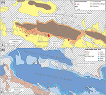 Figure 7. Paleogeographic maps depicting the extent of the Anglo-Polish Super Basin and the facies distribution therein for the Permian, Rotliegend Group (after Doornebal and Stevenson, 2010) (A) and the upper Permian, Zechstein Group (after Gast et al., 2010; Peryt et al., 2010; Patruno et al., 2021) (B). GDE = gross depositional environment.
Other parts of the Anglo-Polish Super Basin also experienced renewed, localized rifting during the Mesozoic, with several local grabens forming during the Early Jurassic (Figure 8) (Ziegler, 1987). The most notable grabens are the Broad Fourteens (Van Wijhe, 1987b; Hooper et al., 1995), West Netherlands, Roer Valley, and Cleveland Basins, all of which are superimposed on the original Anglo-Polish Basin leading to its subdivision into smaller component structural subprovinces (Ziegler, 1987, 1990; Glennie and Underhill, 1998).
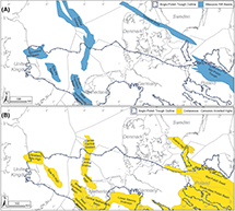 Figure 8. Maps depicting the extent of Mesozoic rift basins (A) and areas affected by Mesozoic and Cenozoic basin inversion that transect and overprint the Anglo-Polish Super Basin precursor (B). The occurrence of successor rift basins causes the primary reservoir targets to be deeply buried, something that causes compaction, diagenesis, and a deterioration in reservoir quality.
The instigation of the North Sea rift system during the Middle Jurassic impacted the Anglo-Polish Super Basin initially through uplift and doming of the area to create the “mid-Cimmerian unconformity” (Underhill and Partington, 1993, 1994) and subsequently by crustal stretching in the Late Jurassic (Figure 8) and postrift-related subsidence thereafter (Underhill, 2003). The development and evolution of the northwest-southeast–striking Central Graben rift arm led to the transection of the North Permian Basin, Mid North Sea high, and Anglo-Polish Basin during the Late Jurassic (Figure 8) (de Lugt et al., 2003; Underhill and Richardson, 2022). The effects of North Sea rift propagation are particularly evident in the Danish and Dutch sectors with the formation of the Tail End graben.
All parts of the super basin were affected by intraplate deformation during the late Mesozoic and Cenozoic in response to far-field plate-margin forces on the Tethyan and Atlantic Oceans (Ziegler, 1987). The most notable effects of which are recorded by phases and varying amounts of uplift and basin inversion (Figure 8) that punctuate the postrift history of subsidence. The effects of the compressional activity led many of the original syn- and postrift depocenters to become structurally elevated and domed (e.g., Van Wijhe, 1987a, b; Baldschuhn et al., 1991; de Jager et al., 1996; de Jager, 2003). The regional uplift that resulted was accommodated by contractional reactivation of numerous rift-related, precursor normal faults (structural inversion) during the Early Cretaceous and Cenozoic (Van Hoorn, 1987; Vejbæk and Andersen, 2002).
In addition to the periods of basin inversion, Brackenridge et al. (2020) have demonstrated that western parts of the basin also experienced a marked easterly tilt during the Neogene resulting in a progressive subcrop toward the United Kingdom coast and the outcrop of formations in the onshore area of Britain (Figures 9, 10). A marked westerly onlap of deltaic sediments onto the unconformity that resulted from the deformation is present (Verweij et al., 2018; Patruno et al., 2020).
 Figure 9. Southwest-northeast–oriented cross section based on a well correlation that transects the English coastline and onshore outcrop patterns (inset). The Bunter Sandstone Formation is shown to crop out to the west of Lincoln, whereas the Leman Sandstone Formation pinches at a depth of approximately 400 m to the west of Whisby. The Bunter Sandstone Formation and the Leman Sandstone Formation onshore rise to shallower depths than the 800 m depth contour, which is the minimum burial for potential carbon capture and storage sites. This well correlation contains information from the Oil and Gas Authority and other third parties, British Geological Survey materials (© United Kingdom Research and Innovation, 2022), and data from the UK Onshore Geophysical Library. This figure includes content supplied by IHS Markit (Copyright © IHS Markit, 2022. All rights reserved). BPU = Base Permian unconformity; LST = limestone; MID. = Middle; SST = sandstone; TVDSS = true vertical depth subsea.
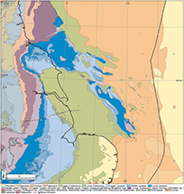 Figure 10. Onshore bedrock geology and offshore sea-bed subcrop for the east coast of England and the Southern North Sea. The colors used for each lithostratigraphic unit can be found in the British Geological Survey’s web portal (https://www.bgs.ac.uk/datasets/bgs-geology/) by navigating to the standard color table. British Geological Survey materials (© United Kingdom Research and Innovation, 2022) are used in this figure. Gp(s). = Group(s).
History of Exploration
Onshore areas of Britain and continental Europe were the initial natural exploration focus, since there was little technology and no regulation to enable subsurface imaging or drilling in offshore waters. The first discovery in the Carboniferous by the Hardstoft well in onshore United Kingdom East Midlands in 1919 led to further discoveries during the 1930s and onward (Lees and Cox, 1937; Lees and Taitt, 1945; Glennie, 1997; Corfield, 2018). Similar success was encountered in onshore areas of the Netherlands, Germany, and Poland, with notable discoveries made in the upper Paleozoic (e.g., the Barnowko-Mostno-Buszewo fields; Antonowicz and Knieszner, 1984; Depowski and Peryt, 1985; Kiersnowski, 1997, 1998; Gorski et al., 1998; Karnkowski, 1999; Arfai and Lutz, 2018) and Mesozoic reservoirs (Doornenbal and Stevenson, 2010). Until the 1960s, the onshore discoveries were considered part of local petroleum systems, with little thought given to the possibility that they may form part of a larger basin that connected the United Kingdom with mainland Europe.
Perceptions changed markedly after the discovery of the Groningen supergiant gas field by the Slochteren-1 and Ten Boer-1 wells in the northwestern Netherlands in 1959 and 1963 (Stäuble and Milnus, 1970; De Jager and Visser, 2017). It was only then that there was a realization that the Permian Rotliegend Group Schlochteren Sandstone reservoir housing the gas in Groningen was equivalent to coastal exposures of the Yellow Sands exposures in northeastern England (Steele, 1983; Smith, 1989, 1994; Chrintz and Clemmensen, 1993), implying that upper Paleozoic (Rotliegend and Carboniferous) reservoirs might extend underneath the Southern North Sea (Glennie, 1998; de Jager and Visser, 2017).
Although there was an increasing appetite to move exploration activity offshore, the prerequisite legislation to govern licensing was not in place. Only a few isolated wells were initially drilled in undisputed nearshore “territorial” waters that extended 5–20 km from the coast. Control over deeper waters that extended to the edge of the continental shelf, defined by the 200-m isobath, remained contested by nation-states. Because the North Sea lay in shallow waters, the countries with a coastal boundary followed the rules of the 1958 Geneva Convention, whereby the median line was equidistant from the nearest opposed coastline. Despite the restrictions that were in place at the time, the existing agreements still allowed for the acquisition of seismic surveys before licensing arrangements were in place. The first offshore survey was shot in Danish waters in 1963 using 50-lb dynamite charges. Some 14,000 km had already been acquired by 1967 (Childs and Reed, 1975).
The Continental Shelf Act (Her Majesty’s Government, 1964) was passed by the United Kingdom Parliament in 1964 and set out the rules for offshore licensing at the time. Similar laws were ratified in Denmark and Germany in the same year, in Norway in 1965, and finally, in the Netherlands in 1968. Although there was consistency in defining quadrants by 1° of latitude and 1° of longitude, there were important differences in the shape and size of individual license blocks. The United Kingdom subdivided its quadrants into 30 blocks of approximately 200 km2; Denmark went for 32 blocks per quadrant; and the Netherlands and Germany settled upon 18 per quadrant.
Having agreed on the size of license blocks and a procedure for exploration and exploitation in offshore waters, the United Kingdom launched the First Seaward Licensing Round on September 17, 1964. The outcome of the application process saw 53 licenses consisting of 394 blocks awarded to 51 companies that formed part of 22 joint-venture consortia. The first offshore licensing round in the Netherlands was held in 1968. In contrast, the first concession in Danish waters covered the entire offshore area and was granted exclusively to A. P. Møller-Maersk in 1962. That was subsequently amended in 1981 and paved the way for the first Danish offshore licensing round to occur in 1984. No formal licensing rounds have ever been held in offshore waters of Germany, and individuals, corporate bodies, or commercial partnerships have been able to apply at any time.
The first well drilled in United Kingdom licensed acreage was the Amoseas’ 38/29-1 well, spudded in the Dogger Bank area on December 26, 1964. Drilled approximately 200 km east of the English coast in what is now recognized as the Mid North Sea high (i.e., outside and to the north of the Anglo-Polish Super Basin), it was plugged and abandoned as a dry hole. Twelve other wells followed, all of which were drilled farther south within the bounds of the Anglo-Polish Super Basin, in the shallow waters of the Southern North Sea. The fourth of the wells in the United Kingdom sector, British Petroleum’s (BP) 48/6-1, discovered gas in Permian (Rotliegend) sandstones (in what was to become the West Sole field) in 1965, paving the way for the offshore waters to be offered for licensing. Further exploration success quickly followed with the discovery of the Viking field (by Conoco), Leman and Indefatigable fields (by Amoco and Shell), and the Ann and Deborah fields (by Phillips Petroleum).
Discoveries were also made in Lower and Middle Triassic sandstones at Esmond, Forbes, and Gordon (Bifani, 1991) and upper Permian (Zechstein Group) carbonates in the Hewett field during the first phase of exploration (Cumming and Wyndham, 1975; Cooke-Yarborough, 1991; Cooke-Yarborough and Smith, 2003). The drilling of the Triassic structures reflected the fact that imaging, depth conversion, and accurate structural mapping of the shallow (suprasalt) section was easier than beneath the Zechstein salt. However, the lack of success when drilling other valid Triassic structures—attributed to a lack of access to charge—soon led to a focus remaining on upper Paleozoic (Permian and Carboniferous) presalt targets.
Drilling for Rotliegend, Leman Sandstone Formation targets in northern areas of the basin rapidly led to a recognition that there was a depositional limit to the clastic reservoir play fairway. However, replacement of the sandstones by claystones set up a new opportunity where Carboniferous reservoirs were sealed by mudstones draping the BPU with a consequent upsurge in wells targeting the pre-Permian and the discovery of several fields in the 1980s in the Silverpit area. Several fields were subsequently developed in the 1990s, including the Schooner, Ketch, Boulton, and Topaz fields.
Petroleum Systems
Source Rocks
It has long been assumed that the main source of the basin’s dry gas was derived from the upper Carboniferous (Stephanian and Westphalian) Coal Measures Group. However, the recent discovery of gas in areas where coal-bearing sequences are absent through erosion by the BPU (e.g., in the Breagh field and Pensacola discovery) has led to a greater appreciation of the contribution made by deeper intra-Carboniferous (Namurian and Dinantian) shale-prone source rocks equivalent to the Bowland or Hodder Shale that charges the fields in onshore areas (Besly, 2018; Grant et al., 2020a) and in the Liverpool Bay area of the East Irish Sea (Chedburn et al., 2022).
The occurrence of Lower Jurassic (Lias Group, Posidonia Shale, and equivalent formations) and Upper Jurassic (Kimmeridge Clay Formation) source rocks in the rift systems that crosscut the Anglo-Polish Basin has led to a local charge (e.g., in the Broad Fourteens and West Netherlands Basins and the Dutch Central and Tail End graben areas). However, the volumes discovered are much smaller than those derived from the Carboniferous source rocks (and Zechstein ones locally, too). They are not sufficient on their own to justify a super basin classification, and although it is appreciated that they make an important contribution in local areas, the focus of this paper is on the larger volumes attributed other stratigraphic intervals, especially the reservoirs belonging to the Permian Rotliegend Group and Triassic Bacton Group.
Prospective Reservoirs
Several reservoir play fairways dominate the super basin (Figure 11), the trapping styles for and geographical extent of which have become increasingly well defined (Figures 11–13). The upper Permian Zechstein Group evaporites form an effective level detachment separating different structural styles that form below from those that characterize its overburden (Figure 12). The most significant stratigraphic intervals in the United Kingdom sector occur both in the subsalt and suprasalt section and are (from oldest to youngest) the Carboniferous, Permian (Rotliegend Group), Permian (Zechstein Group), and Triassic (Bacton Group) (Figure 12), each of which will be discussed in turn.
 Figure 11. The geographical extent of the main play fairways (Carboniferous, Rotliegend Group [early Permian], Zechstein Group [late Permian], and Triassic) within the United Kingdom part of the Anglo-Polish Super Basin. This map contains information sourced from the North Sea Transition Authority, the British Geological Survey materials (© United Kingdom Research and Innovation, 2022), and other third parties.
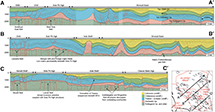 Figure 12. Southwest-northeast–striking poststack time migrated seismic cross sections illustrate the role of the upper Permian Zechstein evaporites in decoupling the structural styles above and beneath them. The sections use PGS‘s Southern North Sea MegaMerge three-dimensional seismic volume and are displayed with a 5× vertical exaggeration. The values displayed on the vertical axis are milliseconds two-way traveltime. BCU = Base Cretaceous unconformity; DGS = Dowsing Graben System; EMS = East Midlands shelf; Gp. = Group; undiff. = undifferentiated stratigraphy.
 Figure 13. A series of schematic cross sections through key hydrocarbon fields exemplifying the main structural styles and their control on the principal plays in the Anglo-Polish Super Basin (after Lambert, 1991; Brook et al., 2003a, b; Hillier, 2003; Peryt et al., 2010; Besly, 2018). (A) Esmond Field, a typical salt-cored anticline formed by halokinesis of the Zechstein Group; (B) Palaeogeomorphic traps hosting Zechstein Group carbonate reservoirs of the Barnowko and Buszewo fields in Poland; (C) Subsalt structures hosting Rotliegend Group, Leman Sandstone Formation reservoirs of the Viking and Victor fields; (D) The Leman supergiant gas field; (E) Carboniferous plays formed by truncation beneath the Base Permian unconformity and intraformational anticlinal folds resulting from Late Pennsylvanian (Variscan) folding in the Boulton field. Gas accumulations are depicted in red diagonal stripes, oil fields with green diagonal ones. The various subcompartments of the Viking field hosting the Rotliegend, Leman Sandstone reservoir (cross section C) and Boulton field hosting Carboniferous reservoirs (cross section E) are shown with corresponding letters in quotation marks. BSh = Bunter Shale; BSt = Bunter Sandstone; CM = Coal Measures; Fm. = Formation; Gp. = Group; MG = Millstone Grit; PG = Penarth Group; RG = Rotliegend Group; volc. = volcanics; ZG = Zechstein Group.
The Carboniferous reservoir targets form the oldest reservoir intervals in the Southern North Sea. The productive formations span an approximately 40 m.y. stratigraphic interval from Dinantian (Middle Mississippian) to Westphalian (Middle Pennsylvanian) stages of the Carboniferous. The reservoirs comprise continental (fluvial-deltaic) and marine clastic systems (Cameron et al., 1992) that are either (1) variably truncated by the BPU (Figure 13) and overlain by the Rotliegend, Silverpit Claystone Formation or by Zechstein Group evaporites (Bailey et al., 1993) or (2) form intraformational folds independent of and unrelated to erosion by the BPU (Figure 13) (Besly, 2018). The reservoirs experienced significant late Carboniferous burial, major contractional deformation during the Variscan Orogeny and were affected by post-Permian events leading to fields hosting them being highly faulted and compartmentalized. The Carboniferous reservoirs in 27 fields account for >3 TCF of the total gas production.
Mixed aeolian and fluvial red bed clastics belonging to the upper Permian, Rotliegend Group (Leman or Schlochteren Sandstone Formation), are sealed by upper Permian (Zechstein Group) evaporites or by the intraformational Silverpit Claystone Formation. Where the Zechstein evaporites are thick and were mobilized, the traps containing the Rotliegend reservoir are decoupled from the supra-Permian section (as exemplified by the Victor and Viking fields in Figure 13). However, where the Zechstein Group evaporites are thin or absent, the structures show a greater degree of thick-skinned coupling to create larger closures (e.g., Leman and Hewett fields) (Hillier and Williams, 1991; Hillier, 2003).
Reserve estimates and produced volumes for the whole of the Anglo-Polish Basin demonstrate that the Permian Rotliegend Leman Sandstone Formation dominates the play fairways. More than 80% of the produced gas volumes are derived from this reservoir and it hosts several supergiant fields including the Groningen, Leman, and Indefatigable. The volumes and dominance of the Rotliegend play over all others form the basis for our more detailed, retrospective assessment of the drivers behind its success as a petroleum system. They also provide a justification by which to investigate what potential the play has for decarbonization technologies in general and carbon storage in particular.
The upper Permian, Zechstein Group (Zechsteinkalk, Hauptdolomit, and Plattendolomit) carbonates form reservoirs around the basin margins (Figure 7) where they are sealed by overlying evaporites belonging to the halite-dominated Stassfurt, Leine, and Aller Halit Formations and the anhydrite-dominated Werraanhydrit, Basalanhydrit, Hauptanhydrit, and Pegmatitanhydrit Formations (Van Adrichem Boogaert and Burgers, 1983; Van Der Baan, 1990; Cameron et al., 1992; Johnson et al., 1994; Peryt et al., 2010). The carbonate reservoirs, which are commonly complex because of their burial history that leads to a variable diagenetic and structural overprint, meaning that they commonly rely on fractures to be able to produce gas (e.g., Wissey field; Duguid and Underhill, 2010). The occurrence of intraformational source rocks commonly means that petroleum they host can be rich in hydrogen sulfide (Van Der Baan, 1990; Southwood and Hill, 1995).
In eastern parts of the basin, the Zechstein carbonates are characterized by pronounced platforms and pinnacles to create major paleogeographic traps and fields in Germany and Poland (Peryt et al., 2010). The play has recently been chased with the acquisition of new seismic surveys (e.g., along the southern margin of the Mid North Sea high), with exploration success leading to new onshore and offshore discoveries (e.g., at West Newton and Pensacola) and renewed interest in licensing.
Triassic, Bacton Group red bed clastics ascribed to the Bunter Sandstone Formation and Hewitt Sandstone Member are sealed by evaporites and mudstones belonging to the Haisborough Group and Bunter Shale Formation, respectively (Cameron et al., 1992; Johnson et al., 1994). The Triassic reservoirs are hosted in periclinal or domal closures exemplified by the Esmond, Forbes, Gordon, Hunter, and Caister B fields. As regional seismic lines attest, the folded traps were created by the mobility of Permian (Zechstein Group) evaporites, something that also leads to a decoupling of the suprasalt section from subsalt structures (Figures 12, 13). Where the salt is thinner, or where fault linkage with the pre-Zechstein structure occurs, inversion-related structures containing gas-filled Triassic reservoirs are created and charged (e.g., Hewitt and Orwell fields).
Due to the isolation from Carboniferous source rocks in areas where the Zechstein Group evaporites are present, Triassic gas fields rely upon complex migration pathways that enable gas to bypass the salt. In northern areas, the gas charge appears to be related to the occurrence of Cenozoic igneous dykes, which not only enable methane to escape from the upper Paleozoic reservoirs but also introduce contaminants (such as CO2 and nitrogen) to closures containing Triassic reservoirs (Figure 14) (Underhill, 2009). As a result of the restricted access to charge, many Triassic closures are dry, and those that contain gas are commonly underfilled (Underhill, 2009).
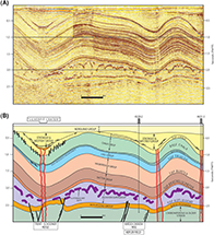 Figure 14. (A) South-southwest–north-northeast–striking uninterpreted seismic dip line and (B) its corresponding geoseismic interpretation showing the occurrence of igneous intrusions (depicted as red vertical lines in (B)) that allow methane gas charge from the subsalt section and introduce CO2 and nitrogen contaminants into salt-cored anticlinal traps that host the Triassic Bunter Sandstone Formation reservoirs (from Underhill, 2009; reproduced with permission of the Geological Society Publishing House). The values on the vertical axis are two-way traveltime in seconds.
The Drive to Decarbonize
The appreciation that greenhouse gas emissions harm the climate has led to a drive to decarbonize. Efforts are being made to tackle emissions from industrial clusters and other hard-to-abate sectors (such as transport and aviation), to encourage and promote new renewable energy sources like hydrogen and geothermal energy and to continue the production of indigenous gas, which has a lower carbon footprint than imports.
A whole host of major industrial sites exist around the North Sea Basin for which a carbon sink is sought including power stations, the location of which is largely a legacy of where coalfields were situated or heavy industry is located. In the case of the United Kingdom, the industrial emissions are primarily centered on six sites at Humberside, Teesside, Grangemouth, Merseyside, South Wales, and Southampton (Figure 15). Twenty-seven percent of emissions come from the Humberside area alone, and around two-fifths of the United Kingdom’s emissions total is from northeastern England (Humberside and Teesside combined; Her Majesty’s Government, 2021; Figure 14). Given the presence of proven traps, reservoirs, and seals in the subsurface in adjacent offshore waters of the Southern North Sea, the Anglo-Polish Super Basin presents the possibility for safe subsurface storage locally. Although no carbon storage sites are yet operating, the appetite to develop opportunities in the United Kingdom sector is clear from the award of seven CCUS licenses (CS001–CS007), four of which lie in the United Kingdom part of the Anglo-Polish Super Basin. The subsequent first offshore carbon storage licensing round offered 13 areas (covering an area >15,000 km2), 8 of which are in the United Kingdom sector of the Anglo-Polish Super Basin.
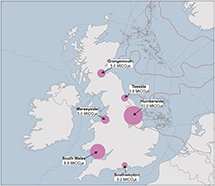 Figure 15. Map showing the distribution of the main industrial emitters in the United Kingdom, the largest of which is Humberside. In combination with Teesside, their occurrence adjacent to depleted fields in shallow, offshore waters of the Southern North Sea sets up the opportunity for carbon storage. The Anglo-Polish Super Basin and its North Permian Basin counterpart are marked by the red outline. The location of offshore fields and the pipeline infrastructure is also depicted. MtCO2e = millions of tons of CO2 equivalent.
The Potential to Extend the Life of the Super Basin through Carbon Storage
The existence of depleted, plugged, and abandoned fields and the existence of other fields that are off their production plateau and are rapidly declining has generated interest in the possibility that they and their (platform, well, and pipeline) infrastructure can be repurposed to play a part in the low-carbon energy transition and the challenge to meet net zero emission targets, which are now enshrined in law in the United Kingdom.
Many low-carbon technologies are being deployed to extend the life of the super basin, including wind power, gas storage, the production of (green and blue) hydrogen, geothermal energy, and CO2 sequestration. Moreover, some fields and uncommercial discoveries contain natural CO2 sourced from Cenozoic igneous dykes and sills (Figure 14) (Underhill, 2009; Underhill et al., 2009; Yielding et al., 2011), and the long-term storage of CO2 is already demonstrable.
We have used traditional geoscientific methods including the application of PBE methods and common-risk segment (CRS) mapping, which are routinely used to investigate petroleum prospectivity, to identify carbon storage fairways and the sweet spots therein, and to assess the potential that individual depleted fields have. Although we have limited our analysis to well-defined closures in this paper, we appreciate that the same approach could be extended to include unconstrained saline aquifer play fairways that have the potential to house even larger volumes of CO2.
Application of Exploration Methods to Identify the Optimal Sites for Carbon Storage
PBE Methods
The PBE approach is the primary method by which explorers understand sedimentary basins, their petroleum systems, and the geological plays contained within them. (Figure 16). Although holistic, PBE has increasingly focused on identifying drill-worthy prospects. As such, it is commonly depicted as a pyramid in which its base addresses the regional foundation, basin context, stratigraphic framework, and petroleum system; the intermediate levels face the need to create and evaluate prospective play fairways; and the apex covers the identification and assessment of individual prospects, many of which may occur within its apposite play fairway.
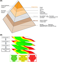 Figure 16. (A) Play-based exploration (PBE) pyramid depicting the three main (basin-, play-, and prospect-scale) levels and the main methods deployed in PBE assessment. The diagram illustrates the stages and workflows involved in the play-based approach to hydrocarbon exploration (Shell Exploration and Production, 2013). The PBE approach forms the basis for common-risk segment (CRS) mapping and creating a composite map to identify prospective sweet spots in a sedimentary basin, where subsequent exploration is highly graded. (B) Schematic cartoon depicting the CRS mapping approach and composite CRS map that results from overlaying each segment. 4-D = four-dimensional.
CRS Mapping
The CRS mapping forms a part of PBE assessments and addresses the level of exploration risk within the play. Individual grids are produced for each of the main elements of the petroleum system (e.g., source, reservoir, seal, trapping style, and charge). The relative confidence of these elements is quantified from geological and seismic data and integrated with well data, structural interpretation, and other relevant technical inputs. The results allow gross depositional environment maps to be drawn that depict the paleogeography of the super basin, the geographical distribution of source rocks, reservoirs, and seals, and the component CRS maps to be constructed. Specific elements affecting prospectivity, including reservoir diagenesis, porosity, and permeability variations, seal effectiveness, and source rock maturity, are commonly integrated into the maps to provide additional granularity.
In addition to the geological inputs, it is common for maps that address data confidence and other nontechnical risks to be integrated into the CRS analysis to present a complete picture of prospectivity. The data-focused maps primarily address the seismic data coverage, how it was acquired (e.g., is it modern, high fidelity, broadband?), and density (e.g., are 3-D seismic volumes or spaced two-dimensional [2-D] grids available?) but may also consider the relative well spacing and assess the amount of core obtained over the key sedimentary intervals.
Other nontechnical aspects like the availability of acreage (is it open or licensed?) and whether infrastructure exists or not (e.g., are there already export pipelines in place, are they available for use, and are they compliant for the transport of carbon dioxide?) can also be important in focusing attention on the areas where exploration can be prosecuted.
Each CRS map is subdivided into low-, medium-, and high-risk domains for each specific geological element. The resultant CRS maps are commonly depicted in a green, yellow, orange, and red “traffic light” system. The overlay of the individual maps allows a single composite CRS map to be produced that highlights the most prospective areas in the basin, termed “sweet spots.”
Although identifying many key elements (e.g., the occurrence of a reservoir-seal pair and robust trap) remains the same, there is an important distinction between the deployment of PBE and CRS methods for petroleum exploration and carbon storage. The occurrence and maturity of a rich source rock, which is essential for a working petroleum system, is irrelevant for CCUS. Instead, since secure subsurface storage is akin to waste disposal, emphasis is on containment in CCUS.
Evaluating Carbon Storage Opportunities
Role of the Zechstein Group Evaporites
Evaporites belonging to the upper Permian, Zechstein Group, form the primary (super)seal for the prolific Rotliegend Leman Sandstone Formation play in the basin. They form the upper parts of many evaporitic (Z) cycles deposited in the basinal areas of the Anglo-Polish Basin, following cyclical marine incursions originating from the Boreal Sea, located to the north of the basin. Each Z cycle is characterized by an initial period of marine flooding that is superseded by progradational and aggregational carbonate deposition that is more pronounced in marginal areas (Figures 17–19) (Grant et al., 2018) before passing up into increasingly evaporitic facies, with some cycles capped by carnallite, sylvite, and other highly soluble minerals. The geographical extent of the salt deposits creates the limit of the Rotliegend play that it seals and provides the basinward limits to the Zechstein Group carbonate reservoir play fairway too (Figures 18, 19) (Fyfe and Underhill, 2023a, b).
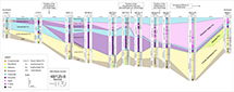 Figure 17. Southwest-northeast–oriented well correlation across the southwest margin of the Anglo-Polish Super Basin. The Zechstein, Z1 to Z3 cycles are highlighted, with the location of the Z1 to Z3 carbonate shelf margins identified. The well correlation has been flattened on the top Plattendolomit Formation (Fm.). The well correlation location corresponds to the line shown in Figure 18. This figure contains information provided by the North Sea Transition Authority’s National Data Repository web portal, and other third parties. SST = Sandstone.
 Figure 18. The geographical location of the shelf margin of the three primary Zechstein carbonates within the United Kingdom Southern North Sea: the Z1 (Zechsteinkalk/Cadeby Formation), the Z2 (Hauptdolomit/Kirkham Abbey Formation), and the Z3 (Plattendolomit/Brotherton Formation). The extent of the Boulby Halite and the Fordon Halite Formations, which are key sealing formations within the Zechstein, are highlighted along with the location of current and offered CO2 appraisal and storage licenses and the location of the Zechstein well correlation panel in Figure 17. This figure contains information provided by the Oil and Gas Authority and other third parties (Fyfe and Underhill, 2023a, b).
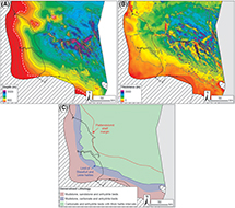 Figure 19. Maps illustrating the depth structure (A), gross thickness (after Peryt et al., 2010) (B), and generalized facies (C) of the Zechstein Group.
The nature and thickness of the Zechstein Group evaporites have led them to be classed as a world-class super-seal, with a high capacity for trapping significant petroleum accumulations (Taylor, 1998). However, some of the thick halite deposits that resulted from the evaporation of the Zechstein Sea experienced significant postdepositional mobility (halokinesis) in response to differential loading and heating resulting from basin subsidence and Cenozoic igneous intrusion (Underhill, 2009). The mobilization of the salt led to the formation of large pillows in some areas and withdrawal synclines in others (Allen et al., 1994). The thinning and, in some cases, welding (touchdown) of the younger section onto the presalt section leads to potential seal risk where direct communication occurs between the pre- and postsalt sections. However, the presence, >300 m thickness, and fine-grained nature of the Bunter Shale Formation means seal integrity is maintained where salt withdrawal and welding occur (Figure 20). Consequently, there is less risk associated with a touch down of Lower Triassic strata onto the Rotliegend–Carboniferous in zones.
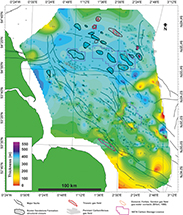 Figure 20. Bunter Shale Formation isochore map derived from well-top point data. The Bunter Shale Formation provides an effective seal for the Rotliegend Group Leman Sandstone reservoir in areas where Zechstein Group halokinesis has led to withdrawal or grounding and welding of the Triassic on to the Rotliegend Group. NSTA = North Sea Transition Authority.
Conversely, the creation of salt-cored anticlines created traps in the supra-Zechstein section leading to some exploration success in the Triassic (Underhill, 2003). The charge for five (Esmond, Forbes, Gordon, Caister B, and Hunter) gas fields took place along Paleogene Age igneous dykes (Underhill, 2009), leading to the Bunter closures hosting CO2 and other contaminants such as nitrogen. Drilling of valid closures located away from the intrusions is invariably water bearing. The depleted fields and the closures hosting saline aquifers are considered carbon storage sites, one of which (Endurance) forms the basis of the Northern Endurance Partnership carbon storage permit. Other depleted fields and dry (water-bearing) closures create other carbon storage targets (Hollinsworth et al., 2022).
Given the crucial role that the upper Permian, Zechstein Group evaporites play in creating the seal for the Rotliegend Group play below and trap formation for structures containing the Bunter Sandstone Formation reservoir above, our evaluation of carbon storage opportunities has been split into the two component parts encompassing the subsalt and suprasalt sections.
EVALUATING UPPER PALEOZOIC (SUBSALT) CARBON STORAGE OPPORTUNITIES
Controls on Carboniferous Carbon Storage Play Fairways
Productive Reservoir Formations
Erosion beneath the BPU has resulted in a variable subcrop, something that made exploration for Carboniferous reservoir targets difficult. Despite the resulting challenges and disappointments, the occurrence of prospective Pennsylvanian and Mississippian sandstone reservoirs create play fairways in United Kingdom Continental Shelf (UKCS) quadrants 44 and 49 (Figure 21) (Kombrink et al., 2010).
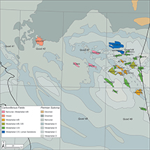 Figure 21. Subcrop patterns below the Base Permian unconformity arising from Variscan foreland folding and differential erosion, the outcome of which sets up Carboniferous plays. The figure shows the distribution of fields hosting Carboniferous Age reservoirs (after Besly, 2018). Quad = Quadrant.
The Westphalian C/D Ketch Formation is the most prolific Carboniferous reservoir interval. It is preserved only within deep (Variscan) synclines. The Ketch Formation forms the main reservoir in gas fields such as Cygnus (400 BCF gas produced), Schooner (310 BCF) and Ketch (250 BCF), though the Cygnus also includes production from its Leman Sandstone reservoir (Catto et al., 2018).
Thicknesses of the Ketch Formation range from approximately 100 m to approximately 400 m (Conway and Valvatne, 2003; Moscariello, 2003; O’Mara et al., 2003a; Dredge and Marsden, 2020; Huis in’t Veld et al., 2020; Moscariello and Goffey, 2020), and it shows a general southwesterly thickening with the thickest intervals preserved in the Schooner and Ketch fields. Detailed field studies have demonstrated that the sandstones were deposited by a northeast-to-southwest–flowing, braided fluvial–deltaic system draining emergent areas of the Mid North Sea high and Rinkobing–Fyn high (Morton et al., 2005). The net-to-gross varies considerably with sandstones representing just 10%–20% of the succession in some Schooner and Ketch wells (Moscariello, 2003; Moscariello and Goffey, 2020) but up to 70% of the succession at Tyne field (Conway and Valvatne, 2003). Sandstone intervals exhibit fairly uniform average porosities across the fields (10%–11%) but highly variable permeabilities spanning several orders of magnitude.
Sandstones belonging to the upper part of the Westphalian A/B Caister Coal Formation (informally referred to as the Murdoch and Caister Sandstone) form reservoirs in the Murdoch (386 BCF gas produced), Chiswick (255 BCF), Caister (187 BCF), McAdam (137 BCF), and Kew (37 BCF) gas fields. The Caister Coal Formation is a heterogeneous unit deposited in a low-gradient delta-plain setting. Fluvial channel sandstone reservoir intervals are interbedded with poor quality reservoir crevasse splay siltstones and nonreservoir floodplain mudstones and swamp coals. Individual sandstone beds are on average 10–20 m in thickness, 10%–11% porosity, and 5 md permeability (Ritchie and Pratsides, 1993; Smit, 2020).
In UKCS quadrant 43, the Cavendish (100 BCF gas produced), Kilmar (60 BCF), and Trent (125 BCF) gas fields have reservoirs across the Westphalian A and older, Namurian intervals. Within these fields, stacked fluvial channels/distributary channels of the Millstone Grit Group form the older reservoir intervals. At Cavendish and Trent fields, the producing reservoir is Marsdenian (upper Namurian) in age (O’Mara et al., 2003a, b; Wasielka et al., 2020), whereas Kilmar produces from Chokerian–Alportian (middle Namuran) sandstones (Milner et al., 2020). Reservoir intervals are limited to relatively thin (10–20 m) sequences of stacked sandstones with average porosities of ∼12% but low average permeabilities of
On the Mid North Sea high (northern parts of UKCS quadrants 42–44), the BPU cuts down to the Visean, where a single, important, gas discovery (Breagh) has been made within Dinantian–Namurian sandstones (Yoredale Formation) (Grant et al., 2020a; Nwachukwu et al., 2020). To the southeast, younger Namurian and Westphalian sediments are preserved within a syncline below the BPU, with the latter forming the main target in larger Carboniferous gas fields such as Murdoch, Schooner, and Chiswick.
Reservoir Quality
Permeability is a key factor to consider when assessing a potential CO2 storage site. Classical reservoir engineering equations show that reservoir permeability and thickness is proportional to well injectivity (Dake, 1983), and with that in mind, CO2 storage screening studies commonly incorporate a lower permeability cutoff (Kovscek, 2002; Ramírez et al., 2010; Raza et al., 2016; Callas et al., 2022). Most studies call for average permeabilities of 100 md or greater, though some suggest 10 md is sufficient (e.g., Callas et al., 2022). In general, low-permeability CO2 reservoirs should be avoided because they will require an order of magnitude more injection wells (Cinar et al., 2008), and the low injectivity could also cause retainment issues if bottomhole pressures rise to approach the fracture pressure of the formation.
Carboniferous sandstones exhibit average permeabilities of mostly less than 50 md (though actual ranges span several orders of magnitude from 2 storage site. Their reduced permeability can be explained mostly by their complex burial history, including rapid immediate burial, (late Carboniferous) exhumation, and later deep burial and as a result, substantial diagenetic modification including authigenic clay growth (Cowan, 1989; O’Mara et al., 2003b) and burial compaction (Bailey et al., 1993; Wasielka et al., 2020).
Reservoir Compartmentalization
Carboniferous fields have also demonstrated to be heavily compartmentalized in terms of either discontinuous sand bodies, structural faulting, or both. Several gas fields have experienced issues relating to reservoir connectivity, commonly resulting in disappointing gas production (Moscariello and Goffey, 2020). This is in part controlled by paleogeographic setting whereby reservoirs positioned to the northeast of the fairway (proximal to the sediment source area) are higher net-to-gross with more sand-body connectivity than those positioned to the southwest (distal to the sediment source). This has been observed in well recovery rates where those drilled in proximal fields (Boulton, Murdoch, and Ketch) commonly outperform those in the distal region (Schooner, Topaz).
The fields are also commonly structurally complex with elements of both structural and stratigraphic trapping. Many fields consist of multiple fault blocks that have experienced later uplift to produce a broad anticlinal structure. Cases have been documented where faults are thought to impede gas flow (e.g., Schooner field; Moscariello and Goffey, 2020) or delineate pressure-isolated compartments with different free-water levels (e.g., Cygnus field; Dredge and Marsden, 2020). Work undertaken onshore United Kingdom corroborates this, including detailed fault mapping of Carboniferous coal fields (Bailey et al., 2005) and mapping of Carboniferous shale gas targets (de Jonge-Anderson and Underhill, 2020).
Structural and stratigraphic compartmentalization brings several challenges to CO2 injection, both from an economic and reservoir management perspective. A reservoir target comprising pressure-isolated compartments will ultimately require more injection wells than a less-compartmentalized reservoir. Furthermore, there are stress and pressure implications because compartmentalization risks rapid pressure buildup and unpredictable stress behavior within the reservoir.
Seal Integrity
Carboniferous sequences in the Silverpit Basin are unconformably overlain by two regional, thick, low/zero-permeability units: the Silverpit Formation (mudstones, siltstones, and halite) and the Zechstein Group (anhydrites, carbonates, and halites) with the former having provided an effective seal for most Carboniferous gas accumulations. However, the trapping geometries of several gas fields necessitate an additional element of intra-Carboniferous sealing. Although this is assumed to be provided by clay-rich, thin, “marine bands,” the precise capacity and integrity of intra-Carboniferous seals remains relatively unknown (Besly, 2018). Given the abundance of low-permeability intervals separating Carboniferous sequences from the Triassic Bunter Sandstone, seal integrity is not considered a major concern for the unit’s CO2 storage prospectivity. The only documented cases of a breach of the Zechstein Group salt seal in the basin result from igneous dyke formation that facilitated gas migration into the Esmond, Forbes, Gordon, Hunter, and Caister B fields (Underhill, 2009).
Seismic Imaging
It is essential that any CO2 storage site be routinely monitored, and this would normally be expected to include the use of repeated seismic surveys to measure the extent of the CO2 plume within the reservoir. High-quality seismic imaging would not only allow geophysicists to recognize any early leakage pathways or unwanted migration outside of the project boundary, but it could also help in verifying that intended volumes and saturations of CO2 have been sequestered. However, seismic imaging of the Carboniferous in the Southern North Sea is extremely challenging, in some cases making for a high degree of uncertainty in defining precise trapping geometries and reservoir presence. In many areas, there is significant structural complexity within the overburden including the withdrawal and swelling of Zechstein Group halites and the ensuing velocity variations, which pose substantial challenges to seismic processing and interpretation of the intervals below (Corbin et al., 2005; Grant et al., 2020a, b). Furthermore, many of the Carboniferous reservoir objectives produce little/no seismic reflectivity and are commonly mapped by combining the nearest seismic marker with gridded well thicknesses (Lynch, 2004). Clearly, if there is significant uncertainty regarding the location of the CO2 reservoir target preinjection, this suggests that the measurement, monitoring, and verification of the carbon storage site using more subtle seismic characteristics (such as attribute analysis) would be unlikely to be achievable.
Controls on Rotliegend Group Carbon Storage Play Fairways
Basin Subsidence, Sedimentology, and Diagenesis
The depth to the Rotliegend Group varies across the basin reflecting the differential synsedimentary subsidence and progressive infill of the Anglo-Polish Super Basin (Figures 22–24). Whereas the greatest thicknesses (approaching 300 m) characterize the main depocenters (e.g., Sole Pit trough), marginal areas and intrabasinal highs, such as the Cleaver Bank high, were relatively sediment starved during the initial stages of deposition (Figure 24) (Alberts and Underhill, 1990). The Sole Pit trough is also one of the best examples of the basin inversion that resulted in forming a major anticline that has brought reservoir targets back to shallower levels and created new traps. The main Permian depocenters continued to subside throughout the Mesozoic to reach their maximum burial depth in the Cretaceous when they began to experience uplift resulting from the far-field effects of Alpine and Atlantic plate margin forces.
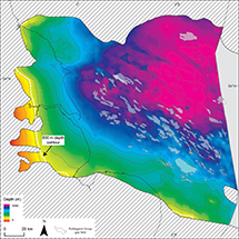 Figure 22. Top Rotliegend depth structure map showing the increasing depth offshore. The 800 m contour below which CO2 is expected to remain in a supercritical phase is shown.
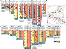 Figure 23. Southwest-northeast–oriented well correlation panels (AB and AC; the locations of which are shown in the inset) flattened at Top Rotliegend Group illustrating the thickening of the Rotliegend Group toward the Silverpit Basin and the shale-out of the Leman Sandstone reservoir. frac. = fraction; GR = gamma ray log; PHIE = effective porosity log; undiff. = undifferentiated stratigraphy.
 Figure 24. Rotliegend Group thickness maps showing the location of the main northwest-southeast–striking axis of deposition (in Sole Pit) and the marked effect that differential subsidence had in controlling depositional thicknesses around its margins (e.g., Inde high, Cleaver Bank, and the East Midlands shelf areas). Updated after Alberts and Underhill (1990) and Doornebal and Stevenson (2010). Carb. = Carboniferous strata; Fm. = Formation; SST = Sandstone.
The primary control on the prospective Rotliegend play fairway is paleogeography and the gross depositional environments that characterize it. Sedimentological analysis of cores from early wells demonstrated that a major erg was positioned along the basin’s southern margin (Figure 25). Although dominated by a desert populated by large barchan dunes, ephemeral braided river systems also characterize some areas, especially those located on the margins of the basin. A major desert lake (salina) developed in more northern areas with dry and wet continental sandy sabkha deposits characterizing the transition to form a waste zone (Figures 23, 25). Recent exploration success (e.g., at Cygnus) has shown that sandstone deposition also characterizes the Rotliegend on the Mid North Sea high flank to create a coarse clastic fringe along the northern margin of the basin (Catto et al., 2018; Dredge and Marsden, 2020).
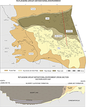 Figure 25. Plan-view map and cross section showing the paleogeographic distribution of the aeolian, continental sandy sabkha, and desert lake (salina) facies in the United Kingdom sector of the Southern North Sea. After Alberts and Underhill (1991) and Doornenbal and Stevenson (2010). FM = Formation; SST = Sandstone.
Reservoir quality is strongly influenced by the different facies assemblages associated with this gross depositional environment, whereby aeolian sandstones of the Leman Sandstone Formation exhibit the best quality, fluvial sandstones exhibit moderate quality, and continental sabkha sandstones/siltstones essentially form a waste zone (Figure 25) (Alberts and Underhill, 1990). The desert lake sediments, ascribed to the Silverpit Claystone Formation, act as an intraformational seal, where it oversteps the Leman Sandstone Formation and for Carboniferous reservoirs truncated by the BPU.
Mesozoic and Cenozoic subsidence and uplift (Figure 26) had a profound effect on the reservoir quality of the Leman Sandstone Formation in places like Sole Pit (e.g., Glennie and Boegner, 1981), leading to a significant reduction in porosity and permeability due to compaction and diagenesis (Figures 27, 28). The burial history means that although the depocenters tend to contain the thickest Leman Sandstone Formation reservoirs, they are also tighter (Figure 27), and thinner, better-quality ones are found in the intrabasinal highs such as the Inde and Cleaver Banks areas (Figure 27) (e.g., Conway, 1986; Alberts and Underhill, 1990) and the marginal wedge that characterizes the southern fringe.
 Figure 26. Isopach maps for each of the main stratigraphic intervals showing the areas of greatest sediment accumulation resulting from differential subsidence. (A) thickness of the Cenozoic sediments; (B) Cretaceous Cromer Knoll and Chalk Group combined thicknesses; (C) Jurassic thicknesses; (D) Triassic Bacton, Haisborough and Penarth Group thicknesses; (E) upper Permian Zechstein Group thickness; (F) Permian Rotliegend Group thickness (after Doornebal and Stevenson, 2010). The Cretaceous and Cenozoic maps also serve to illustrate the effects of erosion and sea-bed subcrop patterns that result from basin inversion and tilting.
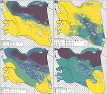 Figure 27. A series of maps summarizing properties relating to the reservoir quality of the Permian, Rotliegend Group, Leman Sandstone Formation. (A) Sandstone net-to-gross ratio expressed as a fraction; (B) sandstone reservoir thickness in meters; (C) sandstone reservoir porosity; (D) sandstone reservoir permeability. Depth structure refers to the depth to the top of the Rotliegend Group and was created using our well-tops database and the surface presented in Gast et al. (2010). Gross thickness is the true vertical thickness of the Rotliegend Group. Net-to-gross is the fraction of sand (shale volume
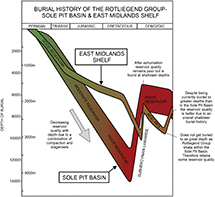 Figure 28. Burial history curves highlighting the variation in subsidence history seen in areas affected by Mesozoic rifting (e.g., Sole Pit) and the intrabasinal highs (e.g., Inde and Cleaver Bank high), the differences between which control compaction, diagenesis, and hence, the porosity and permeability of the reservoir. Subsidence histories adapted from Glennie et al. (1978) and Green (2005). MOD. RES. = moderate reservoir.
This effect is also observed locally, where thickened sediments originally hosted within structural grabens have been buried, diagenetically altered (reducing porosity and permeability), and subsequently uplifted. Such phenomena are believed to be caused by the contractional reactivation of precursor normal faults (structural inversion) to juxtapose sediments that experienced different burial histories (e.g., at Ganymede; Figure 29) (Leveille et al., 1997a, b) leading to many gas fields being highly compartmentalized (Figure 30) (Barr, 2007).
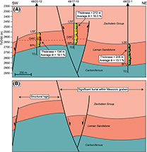 Figure 29. Schematic cross sections through the Ganymede field (after Leveille et al., 1997a, b). The present-day structural high targeted by well 49/17-10 contains thicker but lower porosity sands than adjacent lows. The burial history of the area can explain this. The block lay in the hanging wall to a normal fault active during stages from late Paleozoic to Cretaceous (B). Although a schematic cartoon shows how the reservoir was more deeply buried during the Triassic–Jurassic, leading to a reduction in porosity, no absolute depths have been calculated and hence, values are omitted from the vertical axis. During the Cenozoic (A), the fault was reactivated to form a structural high. Effective porosity logs are shown for each well, where the values range from 0% (cool colors) to 25% (warm colors). Φ = porosity; BPU = Base Permian unconformity; GWC = gas–water contact; LSF = Leman Sandstone Formation; TD = total depth (of the borehole); TVDSS = true vertical depth subsea.
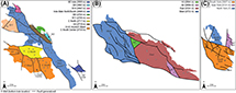 Figure 30. Examples of compartmentalized Rotliegend Group gas fields from (A) Indefatigable (McCrone et al., 2003), (B) Pickerill (de Jonge-Anderson and Underhill, 2022), and (C) York fields (de Jonge-Anderson et al., 2022), all of which were initially assumed to be single accumulations. Following seismic interpretation, drilling, and pressure testing, it became apparent there were multiple, fault-bound compartments with different gas–water contacts, meaning that they were effectively made up of several separate structures.
Structural Controls and Trap Geometry
Interpretation of 3-D seismic volumes has highlighted the occurrence of three main fault trends related to the reactivation of preexisting structures and the initiation of others:
Northwest-southeast–striking (Tornquist) faults were initiated during the Caledonian plate cycle in association with the development of the Tornquist Sea that branched from the southwest-northeast–striking Iapetus Ocean. The two features combine to create the Anglo-Brabant massif. The closure of the Tornquist Sea led to a strong fabric running through the Southern North Sea, with the resulting fractures being reactivated throughout geological history. The northwest-southeast trends control Carboniferous Basin development in onshore areas of eastern England, where they bound major synrift depocenters like the Edale Basin, Gainsborough trough, and Widmerpool Gulf (Corfield et al., 1996).
West-northwest– to east-southeast–striking faults transect the northwest-southeast–striking ones and are interpreted to have resulted from Permian rifting. As with other fault sets, they also experienced reactivation to accommodate periods of extension and contraction (basin inversion).
Southwest-northeast–striking faults—known informally as De Keyser faults, after the geoscientist who first brought attention to them—are mainly confined to the Rotliegend and older section. They were initially harder to detect, and their importance was only appreciated after the advent of 3-D seismic data acquisition and the use of sophisticated seismic attributes. Pressure data showed how they acted as barriers or baffles to flow in fields like Viking (Anston-Race and Ganesh, 2020) and Cygnus (Dredge and Marsden, 2020).
Onshore, across Lincolnshire and East Yorkshire, the Rotliegend Group has not been impacted by significant faults or structural deformation and dips gently to the east, leading to its rise to outcrop in the East Midlands (Figures 9, 10). The only prominent area of deformation is marked by west-east–striking, anastomosing faults that make up the Flamborough Head disturbance and mark the basin-bounding fault system to and zone of structural inversion on the southern side of the Cleveland Basin.
As well as playing a key role in trap formation, faulting has important internal effects on the Leman Sandstone Formation in subsurface structures they host. The aeolian sediments that make up the majority of reservoirs are prone to a style of faulting called granulation seams, which are caused by cataclasis. These peculiar structures form in high-porosity, quartz arenites as a result of strain hardening (Underhill and Woodcock, 1987; Fossen et al., 2007), the impact of which is that numerous granulation seams of small (millimeter scale) displacement form a network of faults rather than displacement accruing on a single throughgoing fault through reactivation (strain softening).
The reduction in grain size, greater angularity, poorer sorting, and reduced porosity that characterize the granulation seams leads to them forming important baffles and barriers in what would otherwise be a connected tank of sandstone (Underhill and Woodcock, 1987). Their small displacement and lack of impact on lithology or chemistry mean that granulation seams are notoriously hard to detect. Yet, their occurrence has led to compartmentalizing fields despite sand-on-sand cross-fault juxtaposition. In the case of the Indefatigable field, at least 13 separate compartments have been reported (Pearson et al., 1991). Such a phenomenon is commonly only recognized following appraisal/production drilling and the conducting of pressure tests and has resulted in “large” gas fields consisting of multiple, smaller accumulations with different pressure characteristics (e.g., Indefatigable, Viking, and Pickerill fields; Figure 30).
Application of PBE and CRS Methods to the Rotliegend Group
The risk ascribed to the Rotliegend Group as a CO2 storage fairway is primarily related to its occurrence, thickness, the porosity/permeability of the reservoir formation (Leman Sandstone), and the integrity of its top seal (Zechstein Group). We have produced a set of screening criteria by which to evaluate the carbon storage potential of the Rotliegend Group (Tables 1–3).

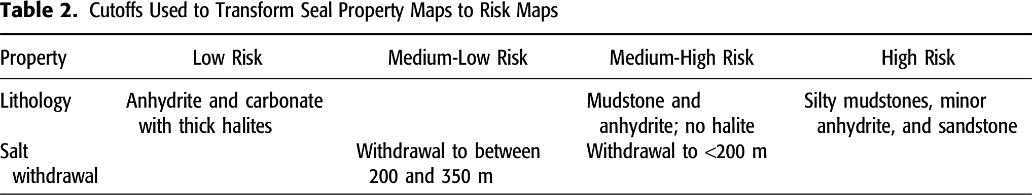
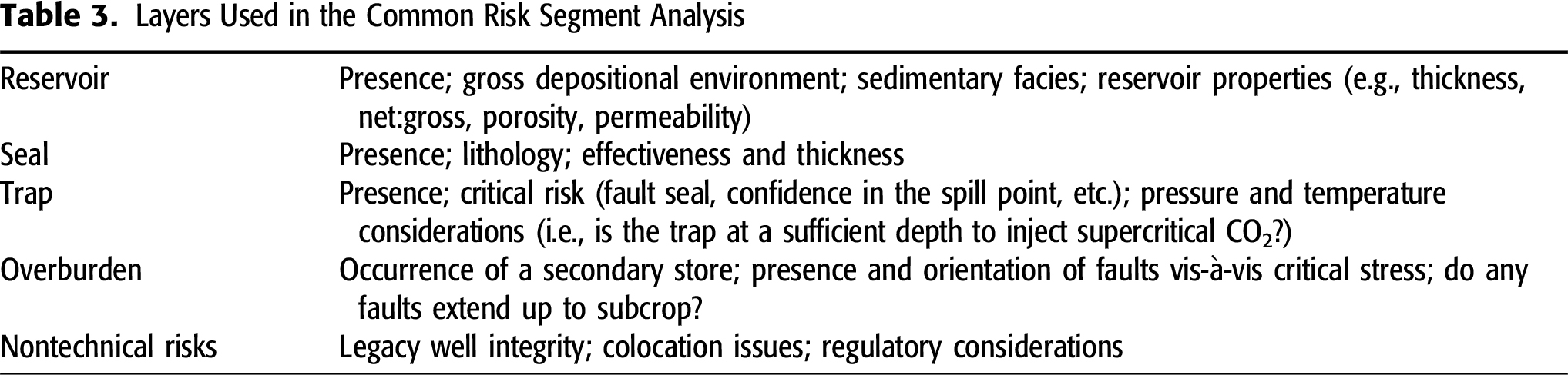
A reservoir risk map highlights the effects of net-to-gross (proportion of sand relative to gross interval), average porosity, and average permeability on the mapped fairway for the formation. The north of the basin is considered mostly high risk with little to no reservoir interval besides an area near the Cygnus field, though the area to the west of this field is relatively unexplored. To the south, net-to-gross is higher (entirely sand-bearing in many areas). Still, areas along the Leman–Silverpit transition zone (“feather-edge”) and within the Sole Pit Basin are ranked higher risk due to their reduced reservoir properties (de Jonge-Anderson et al., 2022). Sandstone deposited on the East Midlands shelf is high net-to-gross but thin and contains a high proportion of fluvial, lower-porosity intervals. From our analysis, the Inde shelf appears to be a reservoir sweet-spot in that the Leman Sandstone is high net-to-gross with many aeolian beds exhibiting moderate porosity and permeability.
The seal risk is a function of both the facies of the Zechstein Group and thickness fluctuations associated with halokinesis. The shelfward limit of the Stassfurt and Leine halites lies to the southwest of the Leman and Hewett fields before passing inland south of the Humber estuary (Fyfe and Underhill, 2023a, b). This limit essentially describes the edge of the low-risk seal area where halites form a resilient and (mainly) thick top seal. To the south and west of this, the Zechstein Group is thinner and composed mainly of platform carbonates, thin anhydrites, or clastics, which are an inherently greater seal risk. Within the basinal areas, halites dominate the succession, but salt withdrawal associated with halokinesis and major diapirs have led to areas where the Zechstein Group is much thinner (
The resulting CRS map combining the reservoir-seal elements for the Rotliegend Group (Figure 31) high-grades the margins that surround the Sole Pit trough: the East Midlands shelf, containing the Rough, Amethyst, and Pickerill fields; the Inde shelf, containing the Sean, Victor, Viking, Audrey, and Sean fields; and the Cleaver Bank high. The edge of Zechstein salts marks the southern boundary, and variations within the Rotliegend fairway are influenced by changes in the reservoir quality (porosity and permeability) from the interplay with the Silverpit Formation and variable pre-Cretaceous burial. The high-graded area includes the Viking carbon capture and storage (CCS) license and areas that were offered in the first United Kingdom CCS round.
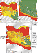 Figure 31. Reservoir-risk (A), seal-risk (B), and common-risk (C) segment maps show the Rotliegend play fairway. The maps are derived from maps of thickness, facies, and petrophysical parameters presented in other figures within this study. Sst. = Sandstone.
As with the Carboniferous, the variable structure and geology of its overburden lead to complex ray paths and depth conversion issues that in turn, lead to poor seismic resolution of the section beneath the salt, something that is likely to impact and impair the seismic monitoring and verification of CO2 injection in Rotliegend reservoirs.
Role of the Zechstein Group Carbonates in Carbon Storage
The carbonate rocks of the Zechstein Group make challenging candidates for potential new CCS sites or for repurposing historic petroleum reservoirs for CO2 storage compared to the Triassic and Permian counterparts. This challenge is due to the highly complex nature of the carbonates, being commonly fractured and having highly variable petrophysical properties over short distances due to complex diagenetic overprints over already highly variable depositional patterns (Underhill and Hunter, 2008; Fyfe and Underhill, 2023a, b). This reservoir heterogeneity could lead to difficulties modeling and monitoring CO2 flow and storage within the reservoirs. Many of the Zechstein petroleum fields are also located onshore, which could raise social concerns about the proximity to population centers. The fields typically have low recovery factors (2.1%–7.7%), which suggests that the potential CO2 storage volumes could be low if the volume of stored gas within the reservoir would not exceed what was initially in place (Fyfe and Underhill, 2023a, b). Currently, there are a lot of unknowns regarding potential chemical reactions between CO2 and carbonate minerals, which have a higher chemical reactivity than siliciclastic minerals (Siqueira et al., 2017). The impacts of injecting vast volumes of CO2 into real-world carbonate reservoirs are poorly understood, with more research needed to understand potential impacts to the reservoir and the overlying seal.
Triassic (Suprasalt) CCUS Opportunities
Whereas the Triassic gas fields (Esmond, Forbes, Gordon, Hunter, and Caister Bunter) are known to contain approximately 1% CO2 (Ketter, 1991; Ritchie and Pratsides, 1993), it is reasonable to assume that the play configuration of the “Bunter closures” have been promoted as either primary or secondary CO2 stores. Despite the relative lack of exploration success and consequently limited number of field developments, the Bunter Sandstone Formation still has a rich legacy of data because it has been penetrated by wells that have targeted upper Paleozoic prospects below.
High-level analysis of the Bunter closures of the Silverpit Basin allows an effective initial screening process to be carried out based on three key parameters: depth to top structure, structure integrity, and closure size (Hollinsworth et al., 2022). However, determining the integrity of the saline aquifer closures in the Silverpit Basin facing Endurance will require a prospect-by-prospect geological and geophysical analysis. In many cases, “exploration” wells and potentially new seismic surveys may be required to test previously untested prospects (e.g., 44/27-CS1 and 43/30-CS1).
Due to the structural position of the Bunter Sandstone Formation above the Zechstein Group, salt mobility (halokinesis) has the potential to place Bunter closures in part or in full above the critical threshold at which CO2 can exist in supercritical form. This relationship is crucial because storage capacity is dramatically reduced where CO2 is stored in a gaseous phase. Secondly, the structure’s integrity cannot be compromised by leaking faults. Some major faults are evident on seismic imaging of the Bunter closures (e.g., 43/11-1 and 43/17-1), resulting in a high risk of potential leakage following injection (without rigorous fault seal analysis). The possibility of minor faults over crestal zones of Bunter closures also exists (e.g., James et al., 2016) that developed in response to flexure caused by underlying halokinesis. Thirdly, closure volume may limit the economic viability of development. Further prospect-specific concerns relating to reservoir properties also exist, including the presence and lateral extent of cemented horizons and shale barriers, that have yet to be addressed.
A recent analysis of the theoretical storage capacity of Bunter closures in the Silverpit Basin indicates that three large closures (exclusive of Endurance) may host the potential to store >1000 million t CO2 (MtCO2) (Hollinsworth et al., 2022). Individually these are less than 50% of the theoretical storage capacity of Endurance (Gluyas and Bagudu, 2020). These structural closures (44/27-CS1, 43/30-CS1, and 44/26-CS1, respectively) lie within the recently awarded license areas (CS006 and CS007) by the North Sea Transition Authority (NSTA). A further six modest closures (8–300 MtCO2) may offer satellite structures to an established CCUS cluster (Hollinsworth et al., 2022). However, three closures identified in the Silverpit Basin fall short of the risk assessment outlined above based on a combination of depth to top crest and severity of faulting (43/11-CS1, 43/17-CS1, and 43/30-CS2).
Many of the Bunter closures that are currently being reviewed for CCS are located offshore to the east of the Dowsing fault zone (Figure 32). To the west of this fault zone, in the vicinity of the currently offered area 3 CCS license in the Southern North Sea, the Bunter Sandstone Formation is generally shown to gently dip upward from offshore toward the onshore outcrop (Figure 4). Any CCS opportunities developed within the Bunter Sandstone Formation in this region will need to make sure there is a valid structural closure, especially on its western margin because if CO2 escaped from a potential CCS site, this CO2 has the potential to migrate from offshore, all the way to the onshore outcrop of the Bunter Sandstone Formation and into the atmosphere.
 Figure 32. Depth structure map for the Bunter Sandstone Formation. The map was created by gridding Bunter Sandstone well tops with a structural trend surface of the top Zechstein Group (Peryt et al., 2010). The white dashed line represents the 800 m contour below which pressure and temperatures are such that carbon dioxide would be expected to remain in its supercritical phase rather than a gaseous one that characterizes shallower depths.
Controls on the Suprasalt (Triassic Bunter Sandstone) Carbon Storage Play Fairways
Geographic Distribution and Sedimentology
The Triassic of the Southern North Sea consists of two component parts: a lower, Bacton Group, which consists of the Hewett Sandstone Member, Bunter Shale Formation, and Bunter Sandstone Formation, and an upper, Haisborough Group that acts as a regional seal for the Bunter Sandstone Formation reservoir.
Regional mapping shows that the Bunter Sandstone Formation lies progressively deeper toward the northeast of the United Kingdom Southern North Sea (Figure 32). As its name implies, the formation is composed of clastic sediments that are representative of coalescing alluvial fans in the west of the basin that transition to sheet flood facies with distal lacustrine shale more prevalent to the east. Following the drawdown of the epeiric Zechstein Sea, the Bunter Sandstone Formation was deposited in a semiarid, thermally subsiding basin, transitionally following from deposition of the playa–lake facies of the underlying Bunter Shale Formation (Cooke-Yarborough, 1991; Cameron et al., 1992; Cameron, 1993; Johnson et al., 1993; Brook et al., 2003a, b; Gluyas and Bagudu, 2020).
Despite its deposition during tectonic quiescence, the top of the formation is defined by the so-called “Hardegsen unconformity,” which is believed to be associated with a phase of intracontinental deformation that occurred in the late Early Triassic (Bachmann et al., 2010). The Bunter Sandstone Formation is thickest across the hanging wall of the Dowsing fault zone. It also thins onto the Mid North Sea high and Dogger shelf to the North and London Brabant massif to the west (Figure 33). Structural deformation during the Mesozoic resulted in the uplift and erosion of Triassic stratigraphy, including the Bunter Sandstone Formation over eastern parts of the area, most notably in the Cleaver Bank high.
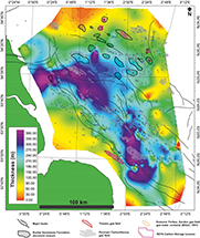 Figure 33. Bunter Sandstone Formation isochore map derived from well top point data showing the differential subsidence that characterizes the northwest-southeast striking Sole Pit trough. NSTA = North Sea Transition Authority.
Reservoir properties of the Bunter Sandstone Formation are generally good to excellent in both gas fields (Cooke-Yarborough, 1991; Ketter, 1991; Ritchie and Pratsides, 1993) and saline aquifers (Brook et al., 2003a, b; Gluyas and Bagudu, 2020). Though conglomerate horizons are present in proximal zones and shale horizons in distal zones, the Bunter Sandstone Formation typically comprises sandstones with porosity >20% and net-to-gross ≥90% (Brook et al., 2003a, b).
The principal historical challenge to the development of gas fields, and likely future hurdles to clear before geological carbon stores can be deployed, is the widespread occurrence of diagenetically derived types of cement, specifically halite. Calcareous, dolomitic, and halite cements are widely recorded in many wells that penetrate the Bunter Sandstone Formation and occur throughout the formation. In extreme cases, laterally continuous hard-cemented layers with thicknesses of several meters are present and can present engineering challenges as well as recovery or displacement of formation waters (Ketter, 1991; Ritchie and Pratsides, 1993; Bentham et al., 2017). Of particular note is a laterally extensive 20–30-m-thick halite-cemented sandstone across the upper boundary of the Bunter Sandstone Formation that covers much of the Silverpit Basin (Gluyas and Bagudu, 2020). Its geographic distribution is easily determined in seismic amplitude maps due to its effect on the acoustic impedance of the top Bunter Sandstone interface. A seismic polarity (or phase) reversal is associated with the extent of the halite-cemented top Bunter Sandstone Formation, separating zones of high-porosity, good reservoir sands (soft interface) from low-porosity zones (hard interface) (Figure 34). This has been suggested by some to be used as an indicator for zones of favorable reservoir quality for CCUS (National Grid, 2016). The phase reversal is also clearly determined from well-log data that can be used to calibrate horizon mapping. Halite-plugged sandstones across the top Bunter Sandstone interface generally show a significant spike in acoustic impedance compared with the overlying Rot Clay and Rot Halite Members. In contrast, uncemented sandstones lack such an acoustic impedance spike (Figure 34). Notably, the mapped extent of the “better” reservoir quality includes the structural closures termed Endurance, 44/26-CS1 (BC36), and 44/27-CS1 (Figure 35).
 Figure 34. Seismic section and correlated well-log plot showing the characteristics of the seismic polarity reversal associated with halite-cemented top Bunter Sandstone (Sst.) Formation (Fm.). The seismic cross section shows the feature on the flanks of the Endurance crest. The well-log plots show two wells penetrating Endurance (42/25d-3) and the nearby 43/17-CS1 structure, approximately 25 km northeast. AI = acoustic impedance; GR = gamma ray; imp = impedance; OBC = ocean bottom cable survey; Synth. = synthetic seismogram; TVDSS = true vertical depth subsea.
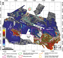 Figure 35. Mean amplitude value map of the top Bunter Sandstone Formation (BSF) seismic reflector. Warm colors (brown to yellow) indicate zones of soft (and hence uncemented) interfaces; cold colors (blues) indicate zones of hard (well-cemented) interfaces. The solid orange line marks the principal seismic polarity transition in areas granted carbon capture, utilization, and storage licenses by the North Sea Transition Authority (NSTA). The positions of structural closures of the Bunter Sandstone are shown in green. 3-D = three-dimensional; imp = impedance; OBC = ocean bottom cable survey; ve = positive to negative seismic polarity.
Structural Controls and Trap Geometry
The predominant trap style of the Bunter Sandstone Formation hydrocarbon and CCUS opportunities are related to doming driven by salt-induced (halokinetic) mobility of the Zechstein Group evaporites (Figure 36) that occurred throughout the Mesoozoic (most notably in Upper Jurassic times) and in the Cenozoic (Ketter, 1991; Ritchie and Pratsides, 1993; Allen et al., 1994; Stewart and Coward, 1995; Underhill, 2009; Pharaoh et al., 2010). This structural configuration is most evident in the Silverpit Basin, spatially associated with the prevailing northwest-southeast structural fabric of the basement underpinning the basin (Figure 37). In this area, reservoir, seal, and trap elements of the Lower Triassic play are all present and in the case of CCUS, largely at sufficient (>800 m) depth for injected CO2 to exist in the supercritical phase (Hollinsworth et al., 2022).
 Figure 36. Seismic panel showing an example of Zechstein Group salt withdrawal from a trough in United Kingdom Continental Shelf block 49/01 and consequent thickening to form structural closure and carbon capture, utilization, and storage prospect 44/26-CS1. The Bunter Shale forms an effective seal for the Rotliegend Group where thinning and touchdown (welding) of the supra- and subsalt section occurs and hence, forms a buffer preventing leakage up into the Bunter Sandstone Formation. The correlated well-log plot shows that the top Bunter Sandstone Formation interface is characterized by a “soft” transition over this area, indicating favorable reservoir properties and a lack of significant cementation. AI = acoustic impedance; Fm. = Formation; GR = gamma ray; Grp. = Group; imp = impedance; Mem. = Member; Sst. = Sandstone; Synth. = synthetic seismogram; TVDSS = true vertical depth subsea; Ucf. = unconformity.
 Figure 37. Location and identifier of mapped Bunter Sandstone Formation closures in the Silverpit Basin, derived from Hollinsworth et al. (2022). Closures 43/08-CS1 (Forbes gas field) and 43/15-CS1 (Gordon gas field) are not included through a lack of three-dimensional seismic coverage resulting in less confidence in determining volumetric components of theoretical storage capacity modeling. Gas field outlines in red indicate the underfilled status of corresponding closures. NSTA = North Sea Transition Authority; TVDSS = true vertical depth subsea.
The Bunter Sandstone Formation is structurally coupled with zones of Zechstein thickening, forming a series of northwest-southeast–oriented ridges and periclinal closures (Figures 36, 37) that offer potential for the geological storage of CO2 in a series of saline aquifers and potentially depleted Triassic gas fields. Geological carbon storage in the Bunter Sandstone Formation has been the focus of research since the early 2000s (Brook et al., 2003a, b; Bentham, 2006) and industry proposals in the form of front-end engineering and development studies to develop three separate prospects: Endurance (National Grid, 2016), Bunter Closure 36 (James et al., 2016), and repurposing the Hewett gas field (E.ON, 2011). Although these initial ventures did not progress to the development stage, a consortium of operators led by BP—dubbed the Northern Endurance Partnership—has successfully procured the first CCUS licenses awarded on the UKCS to develop Endurance and two further areas of the Silverpit Basin in quadrant 43 and quadrant 44. In contrast to the subsalt carbon storage plays that are affected by complex ray paths, higher velocities, and poorer resolution, the relatively shallow level of the Bunter closures has the advantage of enabling four-dimensional (4-D) time-lapse seismic data to be used to measure, monitor, and verify the carbon dioxide plume after injection.
Similar to the Rotliegend, the Bunter Sandstone Formation gently rises to outcrop in the vicinity of York, Nottingham, and Stockton-on-Tees (Figure 4). Onshore to the south of the Flamborough Head fault, there are no significant structural closures to be mapped, in part due to the lack of significant faulting in the region as well as a lack of halokinesis because the area lies beyond the depositional limit of the late Permian evaporites (Fyfe and Underhill, 2023a, b).
Seal Presence and Integrity
A thick sequence of marine mudstones and evaporites of the Middle Triassic Haisborough Group overlies the Bunter Sandstone Formation (Johnson et al., 1994). The Rot Clay Member and Rot Halite Member of the Dowsing Formation form the immediate seal to the Bunter Sandstone Formation and demonstrate effective stratigraphic sealing properties (Ketter, 1991; Ritchie and Pratsides, 1993) as well as structural seals across normal fault blocks (Cooke-Yarborough, 1991). The Haisborough Group is widely present across the Southern North Sea and over many structural closures of the Triassic stratigraphy. However, in areas such as the Cleaver Bank high, erosional truncation associated with the Base Cretaceous unconformity gradually cuts down to Lower Triassic intervals (Alberts and Underhill, 1990).
Since many Bunter closures containing saline aquifers are characterized by crestal faulting, there are challenges to determining the integrity of the seal (Bentham, 2006; Bentham et al., 2013) (Figure 38). These closures were either never charged due to isolation from source or, of more concern for Lower Triassic CCUS opportunities, may have allowed hydrocarbons to escape.
The closures hosting the Bunter Sandstone Formation are better resolved seismically, because they are shallow and located above the salt. The gas fields have direct hydrocarbon indicators (brightening and flat spots), and fluid substitution models suggest the CO2 gas plume would be seen, meaning that injection could be measured, monitored, and verified by 4-D time lapse seismic technology.
One important issue to be addressed with the closures containing the Bunter Sandstone, however, is that its occurrence may limit the structure’s capacity unless it is removed. If it is taken out to allow injection there is then a question as to what to do with it. One option is to remove the saline water from the structure and re-inject it elsewhere, but there have been issues doing so at other sites (e.g., Gorgon in northwest Australia). The position is further complicated in the Southern North Sea because some of the saline formation waters in the Bunter closures (e.g., Endurance) are known to contain contaminants (e.g., zinc and arsenic). Any CO2 injection will lead to their displacement out of the structure, so there is a need to address this issue prior to injection starting.
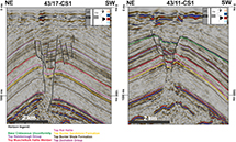 Figure 38. Examples of major crestal faults (black line) with high vertical extent penetrating and offsetting the Bunter Sandstone Formation over closures 43/17-CS1 and 43/11-CS1. imp = impedance.
Ranking Depleted Fields for Carbon Storage
We have constructed bar charts to illustrate the carbon storage opportunity that the depleted fields containing the Carboniferous, Rotliegend Leman Sandstone Formation, and Triassic Bunter Sandstone Formation reservoirs in the Silverpit Basin represent (Figure 39). They depict the cumulative gas production to date for (1) depleted gas fields, (2) producing gas fields, and (3) all gas fields (Figure 39). The bars are colored according to the fields’ reservoir interval, the data for each of which is derived from the NSTA. We appreciate that the “league table” is based on reported total production volumes and will be subject to revision where fields can be shown to be compartmentalized rather than contiguous.
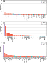 Figure 39. Bar charts illustrating the cumulative gas production to date for depleted gas fields (A), producing gas fields (B), and all gas fields (C). The bars are colored according to the fields’ reservoir interval. The data underpinning the charts is available from the North Sea Transition Authority.
DISCUSSION
Impact of Nongeological Risks on Carbon Storage Opportunities
Well Integrity
Although a geology-led approach has enabled the carbon storage reservoir play fairway and depleted field candidates to be identified in the United Kingdom Southern North Sea, our work has also shown that it is important to be aware of some factors that may prohibit the use of what is otherwise a good geological site.
A particular and significant challenge results from the legacy well stock. After six decades of exploration and development activity, the basin and its fields are peppered by wells. Although all were plugged and abandoned in accord with the regulations about oil and gas activities, almost all were completed before it was envisaged that the subsurface might be repurposed for carbon storage. Some wells may not be optimally configured, and there is a need to understand whether remedial work may be needed and can be undertaken to ensure the well bore is not a leakage pathway to the surface. Identifying imperfect designs may knock out some carbon stores or lead to unforeseen costs resulting from a need to recomplete them or drill expensive sidetracks to intersect and isolate them.
Colocation and the Competition for Offshore Real Estate
A further challenge lies in the increasing competition for offshore acreage to employ decarbonization technologies (Quirk et al., 2022). Recently examples of such conflicts include the Endurance CO2 storage site, which overlaps a planned offshore wind site (Underhill, 2021), and the depleted Pickerill field, which appears to be a robust structure for CO2 storage but is due to be enveloped within another offshore wind site (de Jonge-Anderson and Underhill, 2022).
Fixed wind turbines pose challenges to drilling wells and seismic acquisition activities required to measure, monitor, and verify the CO2 plume. The latter is commonly proposed via the acquisition of regular seismic surveys, which are much cheaper to acquire via a towed streamer rather than fixed ocean-bottom nodes, which introduces significant cost that may adversely affect the commercial case for storage. The former would not be possible with wind turbines fixed on the seabed above the reservoir. With this monitoring in mind, it is also important to know about and factor in the presence of shipping lanes, environmentally protected areas, pipeline and rig infrastructure, and in some cases, any unexploded ordnance.
CO2 Phase
The CO2 must be injected and remain in the reservoir in a supercritical fluid to maximize CO2 storage within potential underground storage sites. This storage requires the reservoir in which the CO2 is being stored to be at a temperature above 31.1°C (88°F) and pressure above 72.9 atm (approximately 1057 psi), which equates to the UKCS to a depth of approximately 800 m. Therefore, any CCS sites shallower than 800 m could be at risk of the CO2 not being stored in its supercritical state. From the mapping of the Bunter Sandstone Formation, there are some structural closures offshore that have a structural crest shallower than 800 m (Figure 37).
The majority of onshore areas, with the exception of eastern parts of Lincolnshire, lie at depths shallower than 800 m with suboptimal storage because it would be in the buoyant, gaseous phase close to population centers and onshore planning regulations. In the past, onshore gas storage facilities around Lincolnshire and East Yorkshire have faced obstacles in bringing the facilities from planning to development due to social objections. Furthermore, with the notable exception of the depleted Caythorpe field, there is a conspicuous absence of structural closures in the region. As a result, developing CCS onshore would be less favorable than developing CCS in offshore locations on the UKCS.
Implications for the United Kingdom’s First Offshore Carbon Storage License Round
Of the 13 offshore licenses offered as part of the first CCUS licensing round, 8 are located in the Southern North Sea, 5 of which lie within the main Rotliegend Group fairway. The Southern North Sea areas 2 and 4 lie on either side of the high-graded Inde shelf and encompass gas fields we consider either low or medium risk. The Southern North Sea areas 6 and 8 encompass fields in the Sole Pit area, which exhibit reduced reservoir properties and are at greater risk. The Southern North Sea area 3 is a large nearshore area with sparse (largely vintage and spaced 2-D) seismic coverage that lacks structural closures and represents a saline aquifer opportunity. We expect the Rotliegend Group to be thin in area 3, with a significant fluvial component in areas like the East Midlands shelf (de Jonge-Anderson et al., 2022). As a result of the tilt of the carbon storage reservoir targets to elevations above 800 m and their eventual rise to outcrop to the west, we consider this moderate-high risk.
The areas offered for license in the first carbon storage round followed the path of least resistance and were deliberately picked to avoid planned or active wind sites and other factors such as sand and gravel extraction, environmental protection, shipping lanes, and unexploded ordnance. Once areas are designated as wind farms with dense, fixed grids, there would be little space available for subsequent licensing rounds within the lower risk areas of the Rotliegend play fairway that we have identified (Figure 40). If the optimal use of the subsurface is sought, there is an urgent need for wind farm operators, those promoting carbon storage, and the regulators to resolve the overlaps and work out which technology gets primacy in the area.
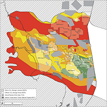 Figure 40. Diagram highlighting the impact of nontechnical risks for carbon storage in the Rotliegend Group. The Rotliegend Group’s green-amber-red (traffic light) color coded common-risk segment map (see Figure 31 for legend) showing the position of existing carbon storage licenses and areas offered as part of the first carbon storage licensing round is overlain by the position of offshore wind sites (active and planned) and conservation zones. The green areas are considered to be the best areas for carbon storage based on geological criteria. The red areas are disadvantaged and the amber ones are intermediate with the potential to house storage sites. JNCC = Joint Nature Conservation Committee; NSTA = North Sea Transition Authority; SNS = Southern North Sea; TCE = The Crown Estate.
Social License to Operate
In addition to the engineering issues, there is also a need not only to seek but also to receive public acceptance and a social license to operate. A highly reactive molecule in the presence of water due to its reaction to form carbonic acid and its potency as an asphyxiant and toxicant require great care to select the best sites for safe subsurface storage. Given the risks, projects must be critically and independently evaluated to provide confidence and assurance. In the first instance, it is suggested that those located away from populated areas and preferably sited offshore are examined first. It is also essential that attention is given to outreach, engagement, and knowledge exchange. Not doing so runs the risk that the public and politicians will reject the technology, as was the case with the Berendrecht CCUS project in the Netherlands (e.g., Brunsting and Mikunda, 2010).
CONCLUSIONS
The Anglo-Polish Super Basin is a major sedimentary basin that stretches from eastern parts of the United Kingdom to central Poland. The resources extracted from the basin allow it to be classified as a petroleum super basin. After a century of onshore exploration and six decades of offshore activity, production is in decline. Although near-field and infrastructure-led exploration continue, attention is turning to field decommissioning and repurposing of the basin to face the energy transition using low-carbon (renewable) technologies that include wind farms, geothermal energy, and carbon storage. The exploration and development data acquired in the pursuit of petroleum provides a solid foundation to evaluate the carbon storage potential of the main gas reservoirs in the basin. The application of PBE methods demonstrates that sandstone reservoirs ascribed to the Permian Rotliegend Group and the Triassic Bunter Sandstone Formation form viable targets for carbon storage in the United Kingdom Southern North Sea, and many areas can be identified. The result allows relative capacity, merits of specific closures, and common technical risks associated with the upper Paleozoic (Permian [Rotliegend] and Carboniferous) subsalt and the Triassic (Bacton Group) suprasalt carbon storage opportunities to be evaluated and quantified. In addition to the geological criteria by which to high-grade areas for carbon storage, the results also highlight the need to factor in nontechnical issues. These include the integrity of the legacy well stock, the competition for offshore areas, especially wind farms fixed to the sea bed, and other environmental impacts, all of which have a potential to constrain the areas available for carbon storage beneath them.
REFERENCES CITED
Alberts, M. A., and J. R. Underhill, 1990, The effect of Tertiary structuration on Permian gas prospectivity, Cleaver Bank area, Southern North Sea, UK, in A. M. Spencer, ed., Generation, accumulation and production of Europe’s hydrocarbons: Houten, the Netherlands, European Association of Petroleum Geoscientists Special Publication 1, p. 161–173.
Allen, M. R., P. A. Griffiths, J. Craig, W. R. Fitches, and R. J. Whittington, 1994, Halokinetic initiation of Mesozoic tectonics in the Southern North Sea: A regional model: Geological Magazine, v. 131, no. 4, p. 559–561, doi:10.1017/S0016756800012164.
Anston-Race, S. E., and D. Ganesh, 2020, The Viking fields, blocks 49/11d, 49/12a, 49/16a, 49/16c, 49/17a, UK North Sea, in G. Goffey and J. G. Gluyas, eds., United Kingdom oil and gas fields: 50th anniversary commemorative volume: Geological Society, London, Memoirs 2020, v. 52, 273–287, doi:10.1144/M52-2018-55.
Antonowicz, L., and L. Knieszner, 1984, Zechstein reefs of the Main Dolomite in Poland: Acta Geologica Polonica, v. 34, no. 1/2, p. 81–94.
Arfai, J., and R. Lutz, 2018, 3D basin and petroleum system modelling of the NW German North Sea (Entenschnabel), in M. Bowman and B. Levell, eds., Petroleum geology of NW Europe: 50 years of learning: Geological Society, London, Petroleum Geology Conference Series 2018, v. 8, p. 67–86, doi:10.1144/PGC8.35.
Bachmann, G. H., M. C. Geluk, G. Warrington, A. Becker, G. Beutler, H. Hagdorn, M. W. Hounslow, , 2010, Triassic, in J. C. Doornenbal and A. G. Stevenson, eds., Petroleum geological atlas of the Southern Permian Basin area: Houten, the Netherlands, European Association of Geoscientists and Engineers Publications, p. 149–173.
Bachmann, G. H., and N. Hoffmann, 1997, Development of the Rotliegend Basin in Northern Germany: Geologisches Jahrbuch D, v. 103, p. 9–31.
Bailey, J. B., P. Arbin, O. Daffinoti, P. Gibson, and J. S. Ritchie, 1993, Permo-Carboniferous plays of the Silver Pit Basin, in J. R. Parker, ed., Petroleum geology of northwest Europe: Geological Society, London, Petroleum Geology Conference Series 2005, v. 4, p. 707–715, doi:10.1144/0040707.
Bailey, W. R., J. J. Walsh, and T. Manzocchi, 2005, Fault populations, strain distribution and basement fault reactivation in the East Pennines Coalfield, UK: Journal of Structural Geology, v. 27, no. 5, p. 913–928, doi:10.1016/j.jsg.2004.10.014.
Baldschuhn, R., G. Best, and F. Kockel, 1991, Inversion tectonics in the north-west German basin, in A. M. Spencer, ed., Generation, accumulation and production of Europe’s hydrocarbons: Houten, the Netherlands, European Association of Petroleum Geoscientists Special Publication, v.1, p. 149–159.
Barr, D., 2007, Conductive faults and sealing fractures in the West Sole gas fields, Southern North Sea, in S. J. Jolley, D. Barr, J. J. Walsh, and R. J. Knipe, eds., Structurally complex reservoirs: Geological Society, London, Special Publications 2007, v. 292, p. 431–451, doi:10.1144/SP292.23.
Benek, R., W. Kramer, T. McCann, M. Scheck, J. Negendank, D. Korich, H. D. Huebscher, and U. Bayer, 1996, Permo-Carboniferous magmatism of the Northeast German Basin: Tectonophysics, v. 266, no. 1–4, p. 379–404, doi:10.1016/S0040-1951(96)00199-0.
Bentham, M., 2006, An assessment of carbon sequestration potential in the UK–Southern North Sea case study: Nottingham, United Kingdom, Tyndall Centre For Climate Change Research Working Paper 85, 36 p., accessed May 17, 2021, http://citeseerx.ist.psu.edu/viewdoc/download?doi=10.1.1.508.6100&rep=rep1&type=pdf.
Bentham, M., A. Green, and D. Gammer, 2013, The occurrence of faults in the Bunter Sandstone Formation of the UK sector of the Southern North Sea and the potential impact on storage capacity: Energy Procedia, v. 37, p. 5101–5109, doi:10.1016/j.egypro.2013.06.423.
Bentham, M., G. Williams, H. Vosper, A. Chadwick, J. Williams, and K. Kirk, 2017, Using pressure recovery at a depleted gas field to understand saline aquifer connectivity: Energy Procedia, v. 114, p. 2906–2920, doi:10.1016/j.egypro.2017.03.1418.
Besly, B., 2018, Exploration and development in the Carboniferous of the Southern North Sea: A 30-year retrospective, in A. A. Monaghan, J. R. Underhill, A. J. Hewett, and J. E. A. Marshall, eds., Paleozoic plays of NW Europe: Geological Society, London, Special Publications 2018, v. 471, p. 17–64, doi:10.1144/SP471.10.
Bifani, R., 1991, Esmond gas complex: Geological Society, London, Special Publications, v. 23, p. 209–221, doi:10.1144/GSL.SP.1986.023.01.1.
Brackenridge, R. E., J. R. Underhill, R. Jamieson, and A. Bell, 2020, Structural and stratigraphic evolution of the Mid North Sea High region of the UK continental shelf: Petroleum Geoscience, v. 26, no. 2, p. 154–173, doi:10.1144/petgeo2019-076.
Breunese, J., J. H. Andersen, S. Brinkman, P. Jagosiak, W. D. Kamin, P. Karnkowski, H. Kombrink, , 2010, Reserves and production history, in J. C. Doornenbal and A. G. Stevenson, eds., Petroleum geological atlas of the Southern Permian Basin area: Houten, the Netherlands, European Association of Geoscientists and Engineers Publications, p. 270–281
Brook, M., K. Shaw, C. Vincent, and S. Holloway, 2003a, Storage potential of the Bunter Sandstone in the UK sector of the Southern North Sea and the adjacent onshore area of eastern England: Keyworth, United Kingdom, British Geological Survey Commissioned Report CR/03/154, 37 p., accessed April 29, 2021, http://nora.nerc.ac.uk/id/eprint/10704/1/CR03154N.pdf.
Brook, M., K. Shaw, C. Vincent, and S. Holloway, 2003b, The potential for storing carbon dioxide in the rocks beneath the UK Southern North Sea, in J. Gale and Y. Kaya, eds., Greenhouse gas control technologies: 6th International Conference on Greenhouse Gas Control Technologies, Kyoto, Japan, October 1–4, 2002, p. 333–338, doi:10.1016/B978-008044276-1/50054-4.
Brunsting, S., and T. Mikunda, 2010, Public participation practice and onshore CCS: Lessons from a Dutch CCS case. Appendix G, in J. Desbarats , eds., Review of the public participation practices for CCS and non-CCS projects in Europe: Deliverable 1.2: NEARCO2, accessed March 30, 2022, http://www.communicationnearco2.eu/fi_leadmin/communicationnearco2/user/docs/Review_of_the_public_participation_practices.pdf.
Callas, C., S. D. Saltzer, J. S. Davis, S. S. Hashemi, A. R. Kovscek, E. R. Okoroafor, G. Wen, M. D. Zoback, and S. M. Benson, 2022, Criteria and workflow for selecting depleted hydrocarbon reservoirs for carbon storage: Applied Energy, v. 324, 19668, 15 p., doi:10.1016/j.apenergy.2022.119668.
Cameron, T. D. J., 1993, Carboniferous and Devonian of the Southern North Sea, in R. W. O’B. Knox and W. G. Cordey, eds., Lithostratigraphic nomenclature of the UK North Sea: Nottingham, United Kingdom, British Geological Survey, v. 5, p. 1–93.
Cameron, T. D. J., A. Crosby, P. S. Balson, D. H. Jeffery, G. K. Lott, J. Bulat, and D. K. Harrison, 1992, The geology of the Southern North Sea: London, British Geological Survey, United Kingdom Offshore Regional Report, 149 p., accessed April 25, 2021, https://pubs.bgs.ac.uk/publications.html?pubID=B01848.
Catto, R., S. Taggart, and G. Poole, 2018, Petroleum geology of the Cygnus gas field, UK North Sea: From discovery to development, in M. Bowman and B. Levell, eds., Petroleum geology of NW Europe: 50 years of learning: Geological Society, London, Petroleum Geology Conference Series 2018, v. 8, p. 307–318, doi:10.1144/PGC8.39.
Chedburn, L., J. R. Underhill, S. Head, and R. Jamieson, 2022, The critical evaluation of carbon dioxide subsurface storage sites: Geological challenges in the depleted fields of Liverpool Bay: AAPG Bulletin, v. 106, no. 9, p. 1753–1789, doi:10.1306/07062221120.
Childs, F. B., and P. E. C. Reed, 1975, Geology of the Dan field and the Danish North Sea, Danmarks Geologiske Undersøgelse III, Række, v. 43, 24 p., doi:10.34194/raekke3.v43.6948.
Chrintz, T., and L. B. Clemmensen, 1993, Draa reconstruction, the Permian Yellow Sands, northeast England, in K. Pye and N. Lancaster, eds., Aeolian sediments, Ancient and modern: Oxford, United Kingdom, International Association of Sedimentologists Special Publication, p. 151–161, doi:10.1002/9781444303971.ch10.
Cinar, Y., O. Bukhteeva, P. R. Neal, W. G. Allinson, and L. Paterson, 2008, CO2 storage in low permeability formations: Society of Petroleum Engineers Symposium on Improved Oil Recovery, Tulsa, Oklahoma, April 20–23, 2008, SPE-114028-MS, doi:10.2118/114028-MS.
Conway, A. M., 1986, Geology and petrophysics of the Victor field, in J. Brooks, J. Goff, and B. Van Hoorn, eds., Habitat of Palaeozoic gas in N.W. Europe: Geological Society, London, Special Publications 1986, v. 23, p. 237–249, doi:10.1144/GSL.SP.1986.023.01.15.
Conway, A. M., and C. Valvatne, 2003, The Boulton field, block 44/21a, UK North Sea, in J. G. Gluyas and H. M. Hichens, eds., United Kingdom oil and gas fields commemorative millennium volume: Geological Society, London, Memoirs 2003, v. 20, p. 671–680, doi:10.1144/GSL.MEM.2003.020.01.53.
Cooke-Yarborough, P., 1991, The Hewett field, blocks 48/28-29-30, 52/4a-5a, UK North Sea, in I. L. Abbotts, ed., United Kingdom oil and gas fields, 25 years commemorative volume: Geological Society, London, Memoirs 1991, v. 14, p. 433–441, doi:10.1144/GSL.MEM.1991.014.01.54.
Cooke-Yarborough, P., and E. Smith, 2003, The Hewett fields: Blocks 48/28a, 48/29, 48/30. 52/4a, 52/5a. UK North Sea: Hewett, Debra, Big Dotty, Little Dotty, Della, Dawn and Delilah fields, in J. G. Gluyas and H. M. Hichens, eds., United Kingdom oil and gas fields commemorative millennium volume: Geological Society, London, Memoirs 2003, v. 20, p. 731–739, doi:10.1144/GSL.MEM.2003.020.01.60.
Copernicus, 2010, European Digital Elevation Model (EU-DEM), version 1.1, accessed June 20, 2023, https://land.copernicus.eu/imagery-in-situ/eu-dem/eu-dem-v1.1.
Corbin, S., S. Gorringe, and D. Torr, 2005, Challenges of developing Carboniferous gas fields in the UK Southern North Sea, in A. G. Doré and B. A. Vining, eds., Petroleum geology: North-west Europe and global perspectives: Geological Society, London, Petroleum Geology Conference Series 2005, v. 6, p. 587–594, doi:10.1144/0060587.
Corfield, S. M., 2018, The first oil exploration campaign in the UK, 1918–22, in J. Craig, F. Gerali, F. MacAulay, and R. Sorkhabi, eds., History of the European oil and gas industry: Geological Society, London, Special Publications 2018, v. 465, p. 39–52; doi:10.1144/SP465.11.
Corfield, S. M., R. L. Gawthorpe, M. Gage, A. J. Fraser, and B. M. Besly, 1996, Inversion tectonics of the Variscan foreland of the British Isles: Journal of the Geological Society, v. 153, no. 1, p. 17–32, doi:10.1144/gsjgs.153.1.0017.
Cowan, G., 1989, Diagenesis of Upper Carboniferous sandstones: Southern North Sea Basin, in M. K. G. Whateley and K. T. Pickering, eds., Deltas: Sites and traps for fossil fuels: Geological Society, London, Special Publications 1989, v. 41, p. 57–73, doi:10.1144/GSL.SP.1989.041.01.05.
Cumming, A. D., and C. L. Wyndham, 1975, The geology and development of the Hewett gas field, in A. W. Woodland, ed., Petroleum and the continental shelf of northwest Europe: London, Applied Science Publishers, p. 313–325.
Dake, L. P., 1983, Fundamentals of reservoir engineering: Amsterdam, Elsevier Science, 464 p.
de Jager, J., 2003, Inverted basins in the Netherlands, similarities and differences: Netherlands Journal of Geosciences, v. 82, no. 4, p. 339–349, doi:10.1017/S0016774600020175.
de Jager, J., 2007, Geological development, in T. E. Wong, D. A. J. Batjes, and J. de Jager, eds., The geology of the Netherlands: Amsterdam, Royal Netherlands Academy of Arts and Sciences, p. 5–26.
de Jager, J., M. A. Doyle, P. J. Grantham, and J. E. Mabillard, 1996, Hydrocarbon habitat of the West Netherlands Basin, in H. E. Rondeel, D. A. J. Batjes, and W. H. Nieuwenhuijs, eds., Geology of gas and oil under the Netherlands: Dordrecht, the Netherlands, Kluwer Academic Publishers, p. 191–209, doi:10.1007/978-94-009-0121-6_17.
de Jager, J., and C. Visser, 2017, Geology of the Groningen field – An overview: Netherlands Journal of Geosciences, v. 96, no. 5, p. S3–S15, doi:10.1017/njg.2017.22.
de Jonge-Anderson, I., A. D. Hollinsworth, J. R. Underhill, and R. J. Jamieson, 2022, A geological assessment of the carbon storage potential of structural closures in the East Midlands shelf, United Kingdom Southern North Sea: AAPG Bulletin, v. 106, no. 9, p. 1827–1853, doi:10.1306/03232221118.
de Jonge-Anderson, I., and J. R. Underhill, 2020, Structural constraints on Lower Carboniferous shale gas exploration in the Craven Basin, NW England: Petroleum Geoscience, v. 26, no. 2, p. 303–324, doi:10.1144/petgeo2019-125.
de Jonge-Anderson, I., and J. R. Underhill, 2022, Use of subsurface geology in assessing the optimal co-location of CO2 storage and wind energy sites: Earth Science, Systems and Society, v. 2, 10055, 20 p., doi:10.3389/esss.2022.10055.
de Lugt, I. R., J. D. van Wees, and T. E. Wong, 2003, The tectonic evolution of the southern Dutch North Sea during the Palaeogene; Basin inversion in distinct pulses: Tectonophysics, v. 373, no. 1–4, p. 141–159, doi:10.1016/S0040-1951(03)00284-1.
Depowski, S., and T. M. Peryt, 1985, Carbonate petroleum reservoirs in the Permian dolomites of the Zechstein, Fore-Sudetic area, western Poland, in P. O. Roehl and P. W. Chocquette, eds., Carbonate petroleum reservoirs: New York, Springer, p. 251–264, doi:10.1007/978-1-4612-5040-1_16.
Doornenbal, J. C., H. Kombrink, R. Bouroullec, R. A. F. Dalman, G. De Bruin, C. R. Geel, A. J. P. Houben, , 2022, New insights on subsurface energy resources in the Southern North Sea Basin area, in S. Patruno, S. G. Archer, D. Chiarella, J. A. Howell, C. A.-L. Jackson, and H. Kombrink, eds., Cross-border themes in petroleum geology I, The North Sea: Geological Society, London, Special Publications 2022, v. 494, p. 233–268, doi:10.1144/SP494-2018-178.
Doornenbal, J. C., and A. G. Stevenson, eds., 2010, Geological Atlas of the Southern Permian Basin Area: Houten, the Netherlands, European Association of Geoscientists and Engineers Publications, 339 p.
Dredge, I., and G. Marsden, 2020, The Cygnus field, blocks 44/11a and 44/12a, UK North Sea, in G. Goffey and J. G. Gluyas, eds., United Kingdom oil and gas fields: 50th anniversary commemorative volume: Geological Society, London, Memoirs 2020, v. 52, p. 151–162, doi:10.1144/M52-2018-69.
Duguid, C., and J. R. Underhill, 2010, Geological controls on Upper Permian Plattendolomite Formation reservoir prospectivity, Wissey field, UK Southern North Sea: Petroleum Geoscience, v. 16, no. 4, p. 331–348, doi:10.1144/1354-0793/10-021.
Duin, E. J. T., J. C. Doornenbal, R. H. B. Rijkers, J. W. Verbeek, and T. E. Wong, 2006, Subsurface structure of the Netherlands: Results of recent onshore and offshore mapping: Netherlands Journal of Geosciences, v. 85, no. 4, p. 245–276, doi:10.1017/S0016774600023064.
EMODnet, 2020, EMODnet digital bathymetry (DTM 2020), doi:10.12770/bb6a87dd-e579-4036-abe1-e649cea9881a.
E.ON, 2011, Kingsnorth carbon dioxide capture and storage demonstration project: Key knowledge reference book: Coventry, United Kingdom, E.ON, 66 p.
Fossen, H., R. A. Schultz, Z. K. Shipton, and K. Mair, 2007, Deformation bands in sandstone: A review: Journal of the Geological Society, v. 164, no. 4, p. 755–769, doi:10.1144/0016-76492006-036.
Fraser, A. J., and R. L. Gawthorpe, 1990, Tectono-stratigraphic development and hydrocarbon habitat of the Carboniferous in northern England, in R. F. P. Hardman and J. Brooks, eds., Tectonic events responsible for Britain’s oil and gas reserves: Geological Society, London, Special Publications 1990, v. 55, p. 49–86, doi:10.1144/GSL.SP.1990.055.01.03.
Fraser, A. J., and R. L. Gawthorpe, 2003, Carboniferous basin development, in A. J. Fraser, A. J. and R. L. Gawthorpe, eds., An atlas of Carboniferous basin evolution in northern England: Geological Society, London, Memoirs 2003, v. 28, p. 13–26, doi:10.1144/GSL.MEM.2003.028.01.03.
Fyfe, L., and J. R. Underhill, 2023a, A regional geological overview of the Upper Permian Zechstein Supergroup (Z1 to Z3) in the SW margin of the Southern North Sea and Onshore Eastern England: Journal of Petroleum Geology, v. 46, no .3, p. 223–256.
Fyfe, L.C., and J. R. Underhill, 2023b, The Upper Permian Zechstein Supergroup of Eastern England and the adjacent Southern North Sea: A review of its role in the UK’s Energy Transition, Journal of Petroleum Geology, v. 46, no. 3, p. 383–406.
Gast, R. E., M. Dusar, C. Breitkreuz, R. Gaupp, J. W. Schneider, L. Stemmerik, M. C. Geluk, , 2010, Rotliegend, in J. C. Doornenbal and A. G. Stevenson, eds., Petroleum geological atlas of the Southern Permian Basin area: Houten, the Netherlands, European Association of Geoscientists and Engineers Publications, p. 101–121.
George, G. T., and J. Berry, 1993, A new lithostratigraphy and depositional model for the Upper Rotliegend of the UK sector of the southern North Sea, in C. P. North and D. J. Prosser, eds., Characterization of fluvial and aeolian reservoirs: Geological Society, London, Special Publications 1993, v. 73, p. 291–319, doi:10.1144/GSL.SP.1993.073.01.18.
George, G. T., and J. K. Berry, 1997, Permian (Upper Rotliegend) synsedimentary tectonics, basin development and palaeogeography of the Southern North Sea, in K. Ziegler, P. Turner, and S. R. Daines, eds., Petroleum geology of the Southern North Sea: Future potential: Geological Society, London, Special Publications 1997, v. 123, p. 31–61, doi:10.1144/GSL.SP.1997.123.01.04.
Glennie, K. W., 1997, History of exploration in the southern North Sea, in K. Ziegler, P. Turner, and S. R. Daines, eds., Petroleum geology of the Southern North Sea: Future potential: Geological Society, London, Special Publications 1997, v. 123, p. 5–16, doi:10.1144/GSL.SP.1997.123.01.02.
Glennie, K. W., 1998, Lower Permian—Rotliegend, in K. W. Glennie, ed., Petroleum geology of the North Sea: Basic concepts and recent advances: Oxford, United Kingdom, Blackwell Science, p. 137–173, doi:10.1002/9781444313413.ch5.
Glennie, K. W., and P. Boegner, 1981, Sole Pit inversion tectonics, in L. V. Illing and G. D. Hobson, eds., Petroleum geology of the continental shelf of north-west Europe: London, Heyden & Son, p. 110–120.
Glennie, K. W., G. C. Mudd, and P. J. C. Nagtegaal, 1978, Depositional environment and diagenesis of Permian Rotliegendes sandstones in Leman Bank and Sole Pit areas of the UK southern North Sea: Journal of the Geological Society, v. 135, no. 1, p. 25–34, doi:10.1144/gsjgs.135.1.0025.
Glennie, K. W., and J. R. Underhill, 1998, Original development and evolution of structural styles, in K. W. Glennie, ed., Petroleum geology of the North Sea: Basic concepts and recent advances: Oxford, United Kingdom, Blackwell Science, p. 42–84, doi:10.1002/9781444313413.ch2.
Gluyas, J. G., and U. Bagudu, 2020, The Endurance CO2 storage site, blocks 42/25 and 43/21, UK North Sea, in G. Goffey and J. G. Gluyas, eds., United Kingdom oil and gas: 50th anniversary commemorative volume: Geological Society, London, Memoirs 2020, v. 52, p. 163–171, doi:10.1144/M52-2019-47.
Gorski, M., M. Trela, and W. Kunicka-Gorska, 1998, Palaeostructure and palaeogeography from 3D seismic interpretation; examples from the Permian Basin in Poland. Petroleum Geoscience, v. 4, no. 3, p. 221–226, doi:10.1144/petgeo.4.3.221.
Grant, R. G., J. R. Underhill, J. Hernández-Casado, S. M. Barker, and R. M. Jamieson, 2018, Upper Permian Zechstein Supergroup carbonate-evaporite platform palaeomorphology in the UK Southern North Sea: Marine and Petroleum Geology, v. 100, p. 484–518, doi:10.1016/j.marpetgeo.2017.11.029.
Grant, R. J., M. G. Booth, J. R. Underhill, and A. Bell, 2020a, Structural evolution of the Breagh area: Implications for Carboniferous prospectivity of the Mid North Sea High, Southern North Sea: Petroleum Geoscience, v. 26, no. 2, p. 174–203, doi:10.1144/petgeo2019-100.
Grant, R. J., J. R. Underhill, J. Hernández-Casado, R. J. Jamieson, and R. M. Williams, 2020b, The evolution of the Dowsing graben system: Implications for petroleum prospectivity in the UK Southern North Sea: Petroleum Geoscience, v. 26, doi:10.1144/petgeo2018-064.
Heeremans, M., M. J. Timmerman, L. A. Kierstein, and J. I. Faleide, 2004, New constraints on the timing of the late Carboniferous-early Permian volcanism in the central North Sea, in M. Wilson, E.-R. Neumann, G. R. Davies, M. J. Timmerman, M. Heeremans, and B. T. Larsen, eds., Permo-Carboniferous magmatism and rifting in Europe: Geological Society, London, Special Publications 2004, v. 223, p. 177–193, doi:10.1144/GSL.SP.2004.223.01.08.
Her Majesty’s Govermnent, 1964, Continental shelf act, accessed May 20, 2020; https://www.legislation.gov.uk/ukpga/1964/29/pdfs/ukpga_19640029_en.pdf.
Her Majesty’s Government, 2021, Industrial decarbonisation strategy: London, Department for Business, Energy and Industrial Strategy/Department for Energy Security and Net Zero Policy Paper, 168 p.
Hillier, A. P., 2003, The Leman field, blocks 49/26, 49/27, 49/28, 53/1, 53/2, UK North Sea, in J. G. Gluyas and H. M. Hichens, eds., United Kingdom oil and gas fields commemorative millennium volume: Geological Society, London, Memoirs 2003, v. 20, p. 761–770, doi:10.1144/GSL.MEM.2003.020.01.63.
Hillier, A. P., and B. P. J. Williams, 1991, The Leman field, blocks 49/26, 49/27, 49/28, 53/1, 53/2, UK North Sea, in I. L. Abbotts, ed., United Kingdom Oil and Gas Fields, 25 Years Commemorative Volume: Geological Society, London, Memoirs, v. 14, p. 451–458, doi:10.1144/GSL.MEM.1991.014.01.56.
Hoffmann, N., J. Pokorski, W. Linders, and G. H. Bachmann, 1997, Rotliegend stratigraphy, palaeogeography and facies in the eastern part of the Central European Basin, XIII International Congress on the Carboniferous and Permian, Part 2, p. 75–86.
Hollinsworth, A. D., I. de Jonge-Anderson, J. R. Underhill, and R. J. Jamieson, 2022, Geological evaluation of suprasalt carbon storage opportunities in the Silverpit Basin, United Kingdom Southern North Sea: AAPG Bulletin, v. 106, no. 9, p. 1791–1825, doi:10.1306/03232221119.
Hooper, R. J., L. S. Goh, and F. Dewey, 1995, The inversion history of the northeastern margin of the Broad Fourteens Basin, in J. G. Buchanan and P. G. Buchanan, eds., Basin inversion: Geological Society, London, Special Publications 1995, v. 88, p. 307–317, doi:10.1144/GSL.SP.1995.088.01.17.
Huis in’t Veld, R., B. Schrijver, and A. Salzwedel, 2020, The Wingate field, blocks 44/23b, 44/24b and 44/19f, UK North Sea: Geological Society, London, Memoirs 2020, v. 52, p. 288–303, doi:10.1144/M52-2018-75.
James, A., S. Baines, and S. McCollough, 2016, D10: WP5A – Bunter storage development plan 10113ETIS-Rep-13-03: Loughborough, United Kingdom, Energy Technologies Institute Report, 378 p., accessed April 16, 2021, https://data.ukedc.rl.ac.uk/browse/edc/fossil/co2capture/CCS_SAP/Reports/D10_Bunter_36_Storage_Development_Plan_Full_V03.pdf.
Johnson, H., G. Warrington, and S. J. Stoker, 1994, Permian and Triassic of the Southern North Sea, in R. W. O’B. Knox and W. G. Cordey, eds., Lithostratigraphic nomenclature of the UK North Sea: Nottingham, United Kingdom, British Geological Survey, v. 6, 172 p.
Karnkowski, P. H., 1994, Rotliegend lithostratigraphy in the central part of the Polish Permian Basin: Geological Quarterly, v. 30, p. 27–42.
Karnkowski, P. H., 1999, Oil and gas deposits in Poland: Kraków, Poland, Wydawnictwo Geosynoptyków “Geos” AGH, 380 p.
Ketter, F. J., 1991, The Esmond, Forbes and Gordon fields, blocks 43/8a, 43/13a, 43/15a, 43/20a, UK North Sea, in I. L. Abbotts, ed., United Kingdom oil and gas fields, 25 years commemorative volume: Geological Society, London, Memoirs 1991, v. 14, p. 425–432, doi:10.1144/GSL.MEM.1991.014.01.53.
Kiersnowski, H., 1997, Depositional development of the Polish Upper Rotliegend Basin and evolution of its sediment source areas: Geological Quarterly, v. 41, no. 4, p. 433–456.
Kiersnowski, H., 1998, Depositional architecture of the Rotliegend Basin in Poland, in M. Narkiewicz, ed., Sedimentary basins analysis of the Polish lowlands: Prace, Poland, Prace Państwowego Instytutu Geologicznego, p. 113–128.
Kockel, F., 1995, Structural and palaeogeographical development of the German North Sea sector: Berlin/Stuttgart, Germany, Gebrüder Bornträger Beiträge zur Regionalen Geologie, 96 p.
Kombrink, H., B. Besly, J. D. Collinson, D. G. den HartogJager, M. Dusar, G. Drozdzewski, P. Hoth, , 2010, The carboniferous, in J. C. Doornenbal and A. G. Stevenson, eds., Petroleum geological atlas of the Southern Permian Basin area: Houten, the Netherlands, European Association of Geoscientists and Engineers Publications, p. 81–99.
Kovscek, A. R., 2002, Screening criteria for CO2 storage in oil reservoirs: Petroleum Science and Technology, v. 20, no. 7–8, p. 841–866, doi:10.1081/LFT-120003717.
Lambert, R. A., 1991, The Victor field, blocks 49/17, 49/22, UK North Sea, in I. L. Abbotts, ed., United Kingdom oil and gas fields, 25 years commemorative volume: Geological Society, London, Memoirs 1991, v. 14, p. 503–508, doi:10.1144/GSL.MEM.1991.014.01.63.
Lees, G.M., and P.T. Cox, 1937, The geological basis of the present search for oil in Great Britain by the D’Arcy Exploration Company, Ltd.: The Quarterly Journal of the Geological Society of London, v. 93, no. 1–4, p. 156–194, doi:10.1144/GSL.JGS.1937.093.01-04.09.
Lees, G. M., and A. H. Taitt, 1945, The geological results of the search for oilfields in Great Britain: The Quarterly Journal of the Geological Society of London, v. 101, no. 1–4, p. 255–317, doi:10.1144/GSL.JGS.1945.101.01-04.12.
Leveille, G. P., R. Knipe, C. More, D. Ellis, G. Dudley, G. Jones, Q. J. Fisher, and G. Allinson, 1997a, Compartmentalization of Rotliegendes gas reservoirs by sealing faults, Jupiter fields area, Southern North Sea, in K. Ziegler, P. Turner, and S. R. Daines, eds., Petroleum geology of the Southern North Sea: Future potential: Geological Society, London, Special Publications 1997, v. 123, p. 87–104, doi:10.1144/GSL.SP.1997.123.01.06.
Leveille, G. P., T. J. Primmer, G. Dudley, D. Ellis, and G. J. Allinson, 1997b, Diagenetic controls on reservoir quality in Permian Rotliegendes sandstones, Jupiter fields area, Southern North Sea, in K. Ziegler, P. Turner, and S. R. Daines, eds., Petroleum geology of the Southern North Sea: Future potential: Geological Society, London, Special Publications 1997, v. 123, p. 105–122, doi:10.1144/GSL.SP.1997.123.01.07.
Lützner, H., 1988, Sedimentology and basin development of intramontane Rotliegend Basins in central Europe: Zeitschrift für Geologische Wissenschaften, v. 16, no. 9, p. 845–863.
Lynch, J. J., 2004, Visualization and interpretation of 3D seismic in the Carboniferous of the UK Southern North Sea, in R. J. Davies, J. A. Cartwright, S. A. Stewart, M. Lappin, and J. R. Underhill, eds., 3D seismic technology: Application to the exploration of the sedimentary basins: Geological Society, London, Memoirs 2004, v. 29, p. 219–225, doi:10.1144/GSL.MEM.2004.029.01.21.
Magoon, L. B., and W. G. Dow, 1994, The petroleum system, in L. B. Magoon and W. G. Dow, eds., The petroleum system—From source to trap: AAPG Memoir 60, p. 3–24, doi:10.1306/M60585C1.
McCrone, C. W., M. Gainski, and P. J. Lumsden, 2003, The Indefatigable field, blocks 49/18, 49/19, 49/23, 49/24, UK North Sea, in J. G. Gluyas and H. M. Hichens, eds., United Kingdom oil and gas fields commemorative millennium volume: Geological Society, London, Memoirs 2003, v. 20, p. 741–747, doi:10.1144/GSL.MEM.2003.020.01.61.
Milner, P. A., P. J. Whailing, J. Ridings, and J. Gill, 2020, The Kilmar field, block 43/22a, UK North Sea, in G. Goffey and J. G. Gluyas, eds., United Kingdom oil and gas fields: 50th anniversary commemorative volume: Geological Society, London, Memoirs 2020, v. 52, p. 241–254, doi:10.1144/M52-2018-50.
Morton, A., C. Hallsworth, and A. Moscariello, 2005, Interplay between northern and southern sediment sources during Westphalian deposition in the Silverpit Basin, Southern North Sea, in J. D. Collinson, D. J. Evans, D. W. Holliday, and N. S. Jones, eds., Carboniferous hydrocarbon resources: The Southern North Sea and surrounding onshore areas: Yorkshire Geological Society Occasional Publication 7, p. 135–146.
Moscariello, A., 2003, The Schooner field, blocks 44/26a, 43/30a, UK North Sea, in J. G. Gluyas and H. M. Hichens, eds., United Kingdom oil and gas fields commemorative millennium volume: Geological Society, London, Memoirs 2003, v. 20, p. 811–824, doi:10.1144/GSL.MEM.2003.020.01.68.
Moscariello, A., and G. Goffey, 2020, The Ketch, Schooner and Topaz fields, blocks 44/26, 44/28, 49/1a and 49/2a, UK North Sea, in G. Goffey and J. G. Gluyas, eds., United Kingdom oil and gas fields: 50th anniversary commemorative volume: Geological Society, London, Memoirs 2020, v. 52, p. 226–240, doi:10.1144/M52-2019-45.
National Grid, 2016, White Rose: K43: Field development report (Technical: storage): London, National Grid, 244 p., accessed April 1, 2021, https://assets.publishing.service.gov.uk/government/uploads/system/uploads/attachment_data/file/531187/K43_Field_Development_Report.pdf.
Neumann, E.-R., M. Wilson, M. Heeremans, K. Spencer, K. Obst, M. J. Timmerman, and L. Kirstein, 2004, Carboniferous-Permian rifting and magmatism in southern Scandinavia, the North Sea and northern Germany: A review, in M. Wilson, E.-R. Neumann, G. R. Davies, M. J. Timmerman, M. Heeremans, and B. T. Larsen, eds., Permo-Carboniferous magmatism and rifting in Europe: Geological Society, London, Special Publications 2004, v. 223, p. 11–40.
Nwachukwu, C. M., Z. Barnett, and J. G. Gluyas, 2020, The Breagh field, blocks 42/12a, 42/13a and 42/8a, UK North Sea, in G. Goffey and J. G. Gluyas, eds., United Kingdom oil and gas fields: 50th anniversary commemorative volume: Geological Society, London, Memoirs 2020, v. 52, p. 109–118, doi:10.1144/M52-2019-15.
O’Mara, P. T., M. Merryweather, and D. S. Cooper, 2003a, The Tyne gas fields, block 44/18a, UK North Sea, in J. G. Gluyas and H. M. Hichens, eds., United Kingdom oil and gas fields commemorative millennium volume: Geological Society, London, Memoirs 2003, v. 20, p. 851–860, doi:10.1144/GSL.MEM.2003.020.01.71.
O’Mara, P. T., M. Merryweather, M. Stockwell, and M. M. Bowler, 2003b, The Trent gas field, block 43/24a, UK North Sea, in J. G. Gluyas and H. M. Hichens, eds., United Kingdom oil and gas fields commemorative millennium volume: Geological Society, London, Memoirs 2003, v. 20, p. 835–849, doi:10.1144/GSL.MEM.2003.020.01.70.
Patruno, S., H. Kombrink, and S. Archer, 2021, Cross-border stratigraphy of the Northern, Central and Southern North Sea: A comparative tectono-stratigraphic megasequence synthesis: Geological Society, London, Special Publications, v. 494, p. 13–83, doi:10.1144/SP494-2020-228.
Patruno, S., V. Scisciani, W. Helland-Hansen, N. D’Intino, W. Reid, and C. Pellegrini, 2020, Upslope-climbing shelf-edge clinoforms and the stepwise evolution of the northern European glaciation (lower Pleistocene Eridanos Delta system, U.K. North Sea): When sediment supply overwhelms accommodation: Basin Research, v. 32, no. 2, p. 224–239, doi:10.1111/bre.12379.
Pearson, J. F. S., R. A. Youngs, and A. Smith, 1991, The Indefatigable field, blocks 49/18, 49/19, 49/23, 49/24, UK North Sea, in I. L. Abbotts, ed., United Kingdom oil and gas fields, 25 years commemorative volume: Geological Society, London, Memoirs 1991, v. 14, p. 443–450.
Peryt, T. M., M. C. Geluk, A. Mathiesen, J. Paul, and K. Smith, 2010, Zechstein, in J. C. Doornenbal and A. G. Stevenson, eds., Petroleum geological atlas of the Southern Permian Basin area: Houten, the Netherlands, European Association of Geoscientists and Engineers, p. 123–147.
Pharaoh, T. C., M. Dusar, M. Geluk, F. Kockel, C. M. Krawczyk, P. Krzywiec, M. Scheck-Wenderoth, H. Thybo, O. Vejbaek, and J.-D. van Wees, 2010, Tectonic evolution, in H. Doornenbal and A. Stevenson eds., Petroleum geological atlas of the Southern Permian Basin area: Houten, the Netherlands, European Association of Geoscientists and Engineers Publications, p. 25–58.
Quirk, D. G., J. R. Underhill, J. G. Gluyas, M. Howe, H. A. M. Wilson, and S. Anderson, 2022, A low-carbon future for The North Sea Basin in Patruno, S., S. G. Archer, D. Chiarella, J. A. Howell, C. A. L. Jackson, and H. Kombrink, eds., Cross-border themes in petroleum geology I: The North Sea: Geological Society, London, Special Publications, v. 494, p. 197–213, doi:10.1144/SP494-2020-236.
Ramírez, A., S. Hagedoorn, L. Kramers, T. Wildenborg, and C. Hendriks, 2010, Screening CO2 storage options in the Netherlands: International Journal of Greenhouse Gas Control, v. 4, no. 2, p. 367–380, doi:10.1016/j.ijggc.2009.10.015.
Raza, A., R. Rezaee, R. Gholami, C. H. Bing, R. Nagarajan, and M. A. Hamid, 2016, A screening criterion for selection of suitable CO2 storage sites: Journal of Natural Gas Science and Engineering, v. 28, p. 317–327, doi:10.1016/j.jngse.2015.11.053.
Rieke, H., D. Kossow, T. McCann, and C. M. Krawczyk, 2001, Tectono-sedimentary evolution of the northernmost margin of the NE German Basin between uppermost Carboniferous and Late Permian (Rotliegend): Geological Journal, v. 36, no. 1, p. 19–37, doi:10.1002/gj.873.
Rieke, H., T. McCann, C. M. Krawczyk, and J. F. W. Negendank, 2003, Evaluation of controlling factors on facies distribution and evolution in an arid continental environment: An example from the Rotliegend of the NE German Basin, in T. McCann and A. Saintot, eds., Tracing tectonic deformation using the sedimentary record: Geological Society, London, Special Publications 2003, v. 208, p. 71–94, doi:10.1144/GSL.SP.2003.208.01.04.
Ritchie, J. S., and P. Pratsides, 1993, The Caister fields, block 44/23a, UK North Sea, in J. R. Parker, ed., Petroleum geology of northwest Europe: Geological Society, London, Petroleum Geology Conference Series 1993, v. 4, p. 759–769, doi:10.1144/0040759.
Ryka, W., 1989, Rotliegendes volcanics, sediment lithologies and paleoenvironments, and Polish Basin history: An overview, in R. W. Boyle, A. C. Brown, C. W. Jefferson, E. C. Jowett, and R. V. Kirkham, eds., Sediment-hosted stratiform copper deposits: St. John’s, Canada, Geological Association of Canada Special Paper, p. 627–633.
Shell Exploration and Production, 2013, Play based exploration: A guide for AAPG’s Imperial Barrel Award participants, accessed July 22, 2022, https://iba.aapg.org/Portals/0/docs/iba/Play_Based_ExplorationGuide.pdf.
Siqueira, T. A., R. S. Iglesias, and J. M. Ketzer, 2017, Carbon dioxide injection in carbonate reservoirs–A review of CO2‐water‐rock interaction studies: Greenhouse Gases Science and Technology, v. 7, no. 5, p. 802–816.
Smit, W., 2020, Chiswick and Kew fields, blocks 49/4a, 49/4b, 49/4c, 49/5a and 49/5b, UK North Sea, in G. Goffey and J. G. Gluyas, eds., United Kingdom oil and gas fields: 50th anniversary commemorative volume: Geological Society, London, Memoirs 2020, v. 52, p. 142–150, doi:10.1144/M52-2018-48.
Smith, D. B., 1989, The late Permian palaeogeography of north-east England: Proceedings of the Yorkshire Geological Society, v. 47, no. 4, p. 285–312, doi:10.1144/pygs.47.4.285.
Smith, D. B., 1994, Geology of the country around Sunderland: London, British Geological Survey Memoir, sheet 21 (England and Wales), 161 p.
Southwood, D. A., and W. O. R. Hill, 1995, The origin and distribution of porosity in the Zechsteinkalk (Upper Permian) of Hewett field, Southern North Sea: Petroleum Geoscience, v. 1, no. 4, p. 289–302, doi:10.1144/petgeo.1.4.289.
Stäuble, A. J., and G. Milnus, 1970, Geology of Groningen gas field, Netherlands, in M. T. Halbouty, ed., Geology of giant petroleum fields: AAPG Memoir 14, p. 359–369, doi:10.1306/M14368C18.
Steele, R. P., 1983, Longitudinal draa in the Permian Yellow Sands of north-east England, in M. E. Brookfield and T. S. Ahlbrandt, eds., Eolian sediments and processes: Amsterdam, Elsevier Developments in Sedimentology 38, p. 543–550, doi:10.1016/S0070-4571(08)70812-4.
Sternbach, C. A., 2018, AAPG Bulletin super basin initiative: AAPG Bulletin, v. 102, no. 3, p. vii–viii, doi:10.1306/pn010818.
Sternbach, C. A., 2020, Super basin thinking: Methods to explore and revitalize the world’s greatest petroleum basins: AAPG Bulletin, v. 104, no. 12, p. 2463–2506, doi:10.1306/09152020073.
Stewart, S. A., and M. P. Coward, 1995, Synthesis of salt tectonics in the Southern North Sea, UK: Marine and Petroleum Geology, v. 12, no. 5, p. 457–475, doi:10.1016/0264-8172(95)91502-G.
Taylor, J. C. M., 1998, Upper Permian—Zechstein, in K. W. Glennie, ed., Petroleum geology of the North Sea: Basic concepts and recent advances: Oxford, United Kingdom, Blackwell, p. 174–211, doi:10.1002/9781444313413.ch6.
Underhill, J. R., 2003, The tectonic and stratigraphic framework of the United Kingdom’s oil and gas fields, in J. G. Gluyas and H. M. Hitchens, eds., United Kingdom oil and gas fields, commemorative millennium volume: Geological Society, London, Memoirs 2003, v. 20, p. 17–59, doi:10.1144/GSL.MEM.2003.020.01.04.
Underhill, J. R., 2009, Role of intrusion-induced salt mobility in controlling the formation of the enigmatic “Silverpit Crater,” UK Southern North Sea: Petroleum Geoscience, v. 15, no. 3, p. 197–216, doi:10.1144/1354-079309-843.
Underhill, J. R., and J. A. Brodie, 1993, Structural geology of Easter Ross Peninsula, Scotland: Implications for movement on the Great Glen fault zone: Journal of the Geological Society, v. 150, no. 3, p. 515–527, doi:10.1144/gsjgs.150.3.0515.
Underhill, J. R., R. A. Gayer, N. H. Woodcock, R. Donnelly, E. J. Jolley, and I. G. Stimpson, 1988, The Dent fault system, northern England—Reinterpreted as a major oblique-slip fault zone: Journal of the Geological Society, v. 145, no. 2, p. 303–316, doi:10.1144/gsjgs.145.2.0303.
Underhill, J. R., and K. L. Hunter, 2008, Effect of Zechstein Supergroup (Z1 Cycle) Werrahalit pods on prospectivity in the Southern North Sea: AAPG Bulletin, v. 92, no. 7, p. 827–851, doi:10.1306/02270807064.
Underhill, J. R., N. Lykakis, and S. Shafique, 2009, Turning exploration risk into a carbon storage opportunity in the UK Southern North Sea: Petroleum Geoscience, v. 15, no. 4, p. 291–304, doi:10.1144/1354-079309-839.
Underhill, J. R., and M. A. Partington, 1993, Jurassic thermal doming and deflation in the North Sea: Implications of the sequence stratigraphic evidence, in J. R. Parker, ed., Petroleum geology of Northwest Europe: Proceedings of the 4th Conference: Geological Society, London, Petroleum Geology Conference Series 1993, v. 4, p. 337–345, doi:10.1144/0040337.
Underhill, J. R., and M. A. Partington, 1994, Use of maximum flooding surfaces in determining a regional control on the Intra-Aalenian (Mid Cimmerian) sequence boundary: Implications for North Sea basin development and Exxon’s sea-level chart, in H. W. Posamentier and P. J. Wiemer, eds., Recent advances in siliciclastic sequence stratigraphy: AAPG Memoir 58, p. 449–484.
Underhill, J. R., and N. Richardson, 2022, Geological controls on petroleum plays and future opportunities in the North Sea Rift Super Basin: AAPG Bulletin, v. 106, no. 3, p. 573–631, doi:10.1306/07132120084.
Underhill, J. R., and N. H. Woodcock, 1987, Faulting mechanisms in high porosity sandstones; New Red Sandstone, Arran, Scotland, in M. E. Jones and R. M. F. Preston, eds., Deformation of sediments and sedimentary rocks: Geological Society, London, Special Publications 1987, v. 29, p. 91–105, doi:10.1144/GSL.SP.1987.029.01.09.
Van Adrichem Boogaert, H. A., and W. F. J. Burgers, 1983, The development of the Zechstein in the Netherlands, in J. P. H. Kaasschieter and T. J. A, Reijers, eds., Petroleum geology of the southeaster North Sea and the adjacent onshore areas: Dordrecht, the Netherlands, Springer, p. 83–92, doi:10.1007/978-94-009-5532-5_8.
Van Der Baan, D., 1990, Zechstein reservoirs in the Netherlands, in J. Brooks, ed., Classic petroleum provinces: Geological Society, London, Special Publications 1990, v. 50, p. 379–398.
Van Hoorn, B., 1987, Structural evolution, timing and tectonic style of the Sole Pit inversion: Tectonophysics, v. 137, no. 1–4, p. 239–284, doi:10.1016/0040-1951(87)90322-2.
van Wees, J. D., R. A. Stephenson, P. A. Ziegler, U. Bayer, T. McCann, R. Dadlez, R. Gaupp, M. Narkiewicz, F. Bitzer, and M. Scheck, 2000, On the origin of the Southern Permian Basin, Central Europe: Marine and Petroleum Geology, v. 17, no. 1, p. 43–59, doi:10.1016/S0264-8172(99)00052-5.
Van Wijhe, D. H., 1987a, Structural evolution of inverted basins in the Dutch offshore: Tectonophysics, v. 137, no. 1–4, p. 171–219, doi:10.1016/0040-1951(87)90320-9.
Van Wijhe, D. H., 1987b, The structural evolution of the Broad Fourteens Basin, in J. V. R. Brooks and K. W. Glennie, eds., Petroleum geology of North West Europe: London, Graham and Trotman, p. 315–323.
Vejbæk, O. V., and C. Andersen, 2002, Post mid-Cretaceous inversion tectonics in the Danish Central Graben – Regionally synchronous tectonic events?: Bulletin of the Geological Society of Denmark, v. 49, p. 129–144, doi:10.37570/bgsd-2003-49-11.
Verweij, J. M., S. N. Nelskamp, J. H. Ten Veen, G. De Bruin, K. Geel, and T. H. Donders, 2018, Generation, migration, entrapment and leakage of microbial gas in the Dutch part of the Southern North Sea Delta: Marine and Petroleum Geology, v. 97, p. 493–516, doi:10.1016/j.marpetgeo.2018.07.034.
Wasielka, N., J. G. Gluyas, H. Breese, and R. Symonds, 2020, The Cavendish field, block 43/19, UK North Sea, in G. Goffey and J. G. Gluyas, eds., United Kingdom oil and gas fields: 50th anniversary commemorative volume: Geological Society, London, Memoirs 2020, v. 52, p. 131–141, doi:10.1144/M52-2019-10.
Yielding, G., N. Lykakis, and J. R. Underhill Jr., 2011, The role of stratigraphic juxtaposition for seal integrity in proven CO2 fault-bound traps of the Southern North Sea: Petroleum Geoscience, v. 17, no. 2, p. 193–203, doi:10.1144/1354-0793/10-026.
Ziegler, P. A., 1987, Late Cretaceous and Cenozoic intra-plate compressional deformation in the Alpine foreland—A geodynamic model: Tectonophysics, v. 137, no. 1–4, p. 389–420, doi:10.1016/0040-1951(87)90330-1.
Ziegler, P. A., 1990, Geological atlas of Western and Central Europe, 2nd ed.: Shell Internationale Petroleum Maatschappij B.V., 239 p.
AUTHORS
John R. Underhill is the director of the Interdisciplinary Centre for Energy Transition and professor of geoscience and energy transition at Aberdeen University, Scotland. He is also the academic executive director of the Centers of Doctoral Training in Oil and Gas and in GeoNetZero and served as Heriot-Watt University’s chief scientist. He populates the Scottish Science Advisory Council and UK Subsurface Task Force. John is a recognized expert on the North Sea Basin and is leading efforts to repurpose it for carbon storage and the energy transition. He has been an AAPG member for almost 40 years, during which time he has received AAPG’s George C. Matson, Grover E. Murray Distinguished Educator, and Ziad Beydoun awards, as well as the Geological Society’s Lyell Medal and their Energy Group’s Silver Medal. He is the corresponding author of this paper.
Iain de Jonge-Anderson has a B.Sc. degree in petroleum geology from the University of Aberdeen (2011), an M.Sc. degree in petroleum geoscience from HWU (2013), and a Ph.D. in unconventional geomechanics (HWU, 2020). His research contribution to this paper was made whilst being a research associate evaluating carbon capture, utilization, and storage (CCUS) opportunities within the United Kingdom Southern North Sea.
Allan Hollinsworth has a B.Sc. degree in earth science (2015) and a Ph.D. in structural geology (2020), both obtained at the University of Glasgow. He undertook research relevant to this paper at HWU whilst undertaking a research project to evaluate CCUS opportunities within the United Kingdom Southern North Sea. He now holds a teaching fellowship at Bristol University.
Laura-Jane Fyfe holds a B.Sc. in geology and an M.Sc. in integrated petroleum geoscience from the University of Aberdeen, where she also completed her Ph.D. in petroleum exploration of Scotland’s inshore west coast basins. As a postdoctoral research associate at the Institute of GeoEnergy Engineering, HWU, she has collaborated with energy companies and academia on research focussing on petroleum exploration and the energy transition.
ACKNOWLEDGMENTS
The authors acknowledge funding from the Net Zero Technology Centre and Shell that enabled the research to be undertaken. We thank Rachel Jamieson for her help and support for the project and SLB for permission to use their Petrel software under academic license. Data access was obtained via the North Sea Transition Authority’s National Data Repository portal, and where gaps existed, additional, proprietary, seismic data was provided by WesternGeco, access to which we acknowledge and appreciate.